Nice, than you for sharing!
I won't be using this for my measurement issue (the other options are much simpler, and i was aiming for less parts, not more), but I'll do some experiments to familiarize myself with bootstrapping
Nice, than you for sharing!
I won't be using this for my measurement issue (the other options are much simpler, and i was aiming for less parts, not more), but I'll do some experiments to familiarize myself with bootstrapping
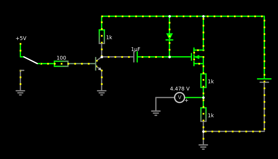
Hm, I don't understand how this is supposed to work - is that a n-channel or p-channel FET?
When I sketch it using falstad's circuitjs, it looks like the FET (n-channel) is a little bit on all the time
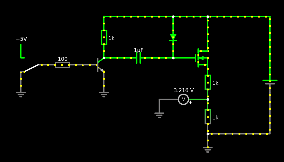
and fully on, when a pulse is applied
Source:
spoiler
$ 1 0.000005 10.20027730826997 50 5 43 5e-11
r 144 80 144 176 0 1000
r 0 192 96 192 0 100
t 96 192 144 192 0 1 -8.999999980890745 9.099999980846458e-10 100 default
c 144 176 304 176 0 0.000001 -1.7996761414451612e-8 0
f 304 176 384 176 32 2 0.02
d 304 80 304 176 2 default
r 384 192 384 272 0 1000
r 384 272 384 352 0 1000
g 384 352 384 384 0 0
g 144 208 144 256 0 0
w 144 80 304 80 0
w 384 160 384 80 0
w 384 80 304 80 0
v 528 256 528 208 0 0 40 9 0 0 0.5
w 528 256 528 352 0
w 528 352 384 352 0
w 528 208 528 80 0
w 528 80 384 80 0
g -48 208 -48 256 0 0
R -48 176 -48 128 0 0 40 5 0 0 0.5
S 0 192 -48 192 0 0 false 0 2
p 384 272 272 272 3 0 0
g 272 272 272 304 0 0
Could you do similar to diagram 2, but instead of an N-FET use a P-FET between the battery and first resistor in the potential divider?
That's a great idea! Unfortunately I don't have a P-FET lying around, so cannot try it right now.
Or use a zener/TVS diode instead of second resistor to clamp the voltage instead of dividing (more robust).
Not sure I understand this point. Which resistor would you replace with a diode?
You could probably increase the 82K and 10K resistors to be much bigger
That's what I thought initially, but this stackoverflow post dissuaded me. The argument there is that the measurement will be wrong, if the input current is not enough to charge the internal cap within the measurement period. But I've done some testing now, and measurements done with 820k and 100k agree well with what my voltmeter measures, so I'll go with this solution!
a fresh alkaline 9V battery is actually 9.6V or more, not 9V.
Indeed! 9.6V * 10k/92k = 1.04V is still below 1.1V, so I should be fine in this case :)
9V battery voltages droop noticeably when under load because of their high internal resistance. Make sure to measure under the same conditions.
This is a good point!
My firmware will be pretty monotonic though, basically:
So, the load should be always the same at step (2).
Could you share a picture? I'm having trouble imagining what you are describing
Call me dumb, but... to me that just sounds like an insecure network, labeled "secure" as long as someone physically guards all the ethernet ports
Best not to eat it.
dang... what else to do with the leftovers then?
Afaik that's a myth. There is no testing or certification associated with the CE logo, it's just a self-declaration of the manufacturer that certain standards are met. You can just buy rolls of these stickers, or print them yourselves. That's what manufacturers do, legit ones and shitty ones.