diyrebel

joined 2 years ago
MODERATOR OF
[–] diyrebel@lemmy.dbzer0.com 5 points 3 months ago* (last edited 3 months ago) (2 children)

Thanks for the suggestion. I’ve seen them in Indian YT videos. I’m half tempted but online shopping is mostly a non-starter for me and I don’t suppose I would find that locally. I bought an Arduino clone and some relays, which might be my nuclear option.

[–] diyrebel@lemmy.dbzer0.com 2 points 3 months ago (3 children)

I spent a lot of time on YT even to the point of watching Arabic videos of my model just to see what actions were taken. I tried the door latch-unlatch trick and unplugging for a long time.. holding the cancel button. Holding the 1st auxillary button. Not sure what else there is to try apart from serial comms.

[–] diyrebel@lemmy.dbzer0.com 1 points 3 months ago (1 children)

I would like to have a scope or logic analyser. Someone told me a logic analyser would be sufficient for this.. and also sufficiently cheap.

I have an Arduino clone but the EEPROM is apparently embedded in the MCU.

[–] diyrebel@lemmy.dbzer0.com 1 points 3 months ago (1 children)

Perhaps I will do that.

But I guess it’s worth mentioning that I have some bad house wiring. I switched off a light to work on it and got shocked (yeah, in principle for safety I should also turn off the breaker but still this should not happen). When lights are off at night, some LED lights are still very faintly lit. When I was messing with serial port wiring I think I touched the 5v and 0v.. perhaps each with a different hand, and felt a shock. 5v should not shock me but I think my ground connections are maybe dodgy. There is proper ground pipes in the basement but maybe someone wired neutral to ground or something somewhere in the house.

[–] diyrebel@lemmy.dbzer0.com 1 points 3 months ago* (last edited 3 months ago)

I assume you measured 5V in reference to the machines GND.

Indeed. It was in fact the 0v pin on the washing machine that is next to the RX pin.

When I meter gnd against 5v on the adapter, I get 5.15v. So both the adapter and the DMM are fine.

I heard that connecting two DC supplies together would have no problem if they both output exactly the same voltage. Of course we would never have an exact match, but the only strain on either side of the connection would be from the difference between the 5v from the adapter and 5v from the washing machine.

~~So I’m tempted to conclude no damage was done and the serial port was sabotaged at the factory.~~

(edit) The w/m also gives 5v. Turns out my alligator clip was bad. So the port may be fine.

[–] diyrebel@lemmy.dbzer0.com 1 points 3 months ago* (last edited 3 months ago) (2 children)

I had the two 5v pins connected (from 5v on the adapter to the 5v pin on the washing machine). I had it that way for maybe 10 or 15 min until I was told not to. The USB→TTL adapter was a little warm when I disconnected it. Now I wonder if I damaged the washing machine port because when I meter the 0v against the 5v, there is almost nothing there. Did I damage it, or did the manufacturer disable the serial port before it got to me?

[–] diyrebel@lemmy.dbzer0.com 2 points 5 months ago* (last edited 5 months ago) (1 children)

I appreciate your insights but struggle to reconcile the following with what others say (youtubers and folks in an electronics chat room):

I doubt many people use eeprom to save any kind of error. … It is far more likely that the script is just a state machine and is reaching an error state because of some missing or bad signal that it needs to continue running the script.

I asked EE folks how would a controller board sense a fault? Does the controller take resistance measurements on the components? The answer was “highly unlikely - that would be far more sophisticated and costly than what would be realistic in a domestic washing machine”. They said fault detection is based on logic. E.g. if the tacho sensor does not have increasing feedback despite increasing power to the motor, then the controller can detect from that that there is a fault. Or if the water has been filling for a long time and the pressure sensor is not detecting a pressure increase, the machine would know from that activity that the inlet valve has a problem.

You seem to suggest that the script reruns from a clean state every time and that a “bad signal” would be re-detected each run, which then implies that the machine would repeatedly attempt to fill with water, tumble, drain, etc. But that does not seem to be what I am seeing. The machine will be powered off & unplugged for days, and when powered on it instantly flashes that there is a fault (which is likely only known after attempting to run the various components). This is consistent with what a Youtuber said: the machine (not my particular model but speaking generally) stores the fault code. From there, the machine is trapped in that state until the error code is cleared by pressing a secret sequence of buttons.

Some leaked tech docs for a different model (same make) mentioned that if a fault occurs 8 times, it then becomes stored in memory. This seems consistent with what I observed. I repeatedly attempted to run the machine. Not sure how many times. Motors would run, failure hits, and then it quits. After doing that so many times (which I regret), the behavior changed. Now the machine will not even attempt to run because it is apparently trapped in an error state.

So everything seems to point to the error code being stored in EEPROM (which I believe is embedded in the ATmega32L chip). And not just the error code but apparently a count of failed attempts to run a program.

[–] diyrebel@lemmy.dbzer0.com 2 points 5 months ago* (last edited 5 months ago) (3 children)

I don’t intend to modify the program. I am just looking to reset the state of the software to get it out of the fault state.

Normally that can be done by using the buttons on the PCB to enter a secret combination code to:

  • enter diagnostic mode
  • run various functions/cycles which normally run as part of a program
  • see the error code
  • reset the board

When the software detects a fault (such as a broken pump), it saves the error code. Then if you fix the pump, the software doesn’t know the pump has been fixed. So the board has to be reset to clear the error code.

The button sequence codes are secret and known only to the manufacturer. They are very protectionist. In Europe, law requires them to make the codes available to other 3rd party technicians -- but only in the 1st ten years and they can also charge a fee. Consumers get no access under any circumstances.

My thought was theoretically a pro independent repair service would not want to pay every manufacturer for the secret info for every model they repair -- so perhaps they would attach to the USART serial port and have a way to see errors and reset the board. But if it’s as you say, then the USART is disabled and useless to repairers. Which means I’m stuffed because I cannot buy a replacement card for my machine.

If the serial port is not disabled, you conjecture that it is likely a read-only non-interactive mechanism. That still may be useful. I was able to find the secret button combination that is likely giving me an error code which I can guess the meaning of based on leaked docs for other models, but I’m not satisfied with that. I would be useful if I could get more verbose or supplemental info about the error state.

There is some chatter about GE washing machines (not what I have) include an rj-45 port and that they released some kind of open source thing called the green bean which adapts USB to serial. On the one hand, it suggests that not all manufacturers intend to prevent communication with the PCB. OTOH, this actually seems to not be for service use but for sending notifications to the user.

[–] diyrebel@lemmy.dbzer0.com 2 points 5 months ago (5 children)

The MCU is an ATmega32L, which seems to be well documented. I was able to fetch a 300+ page document and a 12 page overview of the specs.

[–] diyrebel@lemmy.dbzer0.com 2 points 5 months ago* (last edited 5 months ago)

There is no service manual within my reach. I would have to resort to bribery, torture, breaking and entry, and theft to get one. Thanks for the link but that only seems to cover N.American makes.

This is in fact why I am looking to probe the serial port. To try to poke around since I don’t know the secret steps to reseting the board.

[–] diyrebel@lemmy.dbzer0.com 1 points 6 months ago (1 children)

I appreciate the guidance. But I think I can rule out insulation breakdown because I just removed the cover to the tacho generator and the ring magnet was broken in two pieces.

[–] diyrebel@lemmy.dbzer0.com 1 points 6 months ago* (last edited 6 months ago)

i just see a blank page where an article would go. There is a giant ad at the top and typical garbage down the sides and at the bottom, but no text in the article to read.

(edit) is it just an image? I have images disabled so I wonder if that’s my issue.


My washing machine is dying in stages. It started with the same symptoms as this thread. Specifically, after filling the tube for a wash cycle, it would go straight into a high-speed spin (full of water!) for a second or two (instead of the expected slow tumble), then quit. The speculation is that the tachometer is failing.

Then the machine got worse. I now cannot even start any program. No matter what program I select, I press start and after a few second pause the start button LED just blinks. It’s a generic blunt signal of a fault. The blinks are evenly spaced non-stop, so there is no error code of any kind.

To test the motor, I followed the linked video and took resistance measurements. All seems okay in that regard. Test results:

tachometer

Expectation: any reading that is not infinite/disconnected is fine.

  • (video): 70 Ω
  • (my motor): 52 Ω

carbon brushes:

Expectation: should be in the range 1—7 Ω

  • (video): 5 Ω
  • (my motor): 3.2 Ω

field windings:

Expectation: all combinations should be 1-7 Ω

  • (video): 3.5 Ω
  • (my motor): 2.2 Ω

I do not have whatever model is in that video, but I think the motor is universal and my readings are in the range suggested by the video presenter. But is it fair to say these are crude and incomplete tests? I am expecting the tachometer to be bad based on the behavior.

Motor spin test

My next move was to try to make the motor spin. There is no service manual or wiring diagram for my Beko. So I inspected the motor and derived these pins:

1 brown (field)
2 black (field)
3 blue (field)
4 white (brush)
5 red (brush)
6 yellow (tacho)
7 yellow (tacho)
8 yellow+green (ground)

Someone suggested this wiring:

L → pin 1
N → pin 5
jumper connecting pins 3 & 4

I did not connect direct to the wall because I wanted to use the mechanical power button of the machine to turn on and off the motor (so I could quickly cut power if needed). So power took this path:

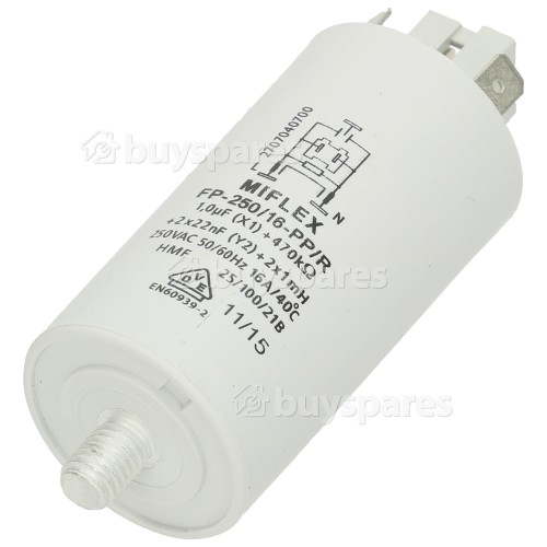
wall (220 VAC) → safety capacitor → mechanical button → motor (wiring redirected to motor instead of control panel)

When I switched it on, the motor spun for 1 or 2 seconds and I saw a white flash (I think) and the motor quit. I turned it off. Then tried to switch it on again. No response.

220 VAC quit coming out of the safety capacitor. Instead the voltage jumped around between 10 VAC and 20 VAC. So I thought I fried the capacitor or resisters therein. I checked the motor to see if any of the pins connected to ground (answer: no, so the motor was no harmed). Then I disconnected the safety capacitor and connected it just to mains and ground. 220 VAC was output (WTF.. why does it work again?)

I think I’m back to the state it was in before I tried to power the motor. But I want to understand why the safety capacitor apparently flashed white and temporarily died with only 10—20vac output. I need to get to the bottom of this because I still need to test the motor for more than 1 second in a way that doesn’t cause more white flashes. Is it a bad idea to have the safety capacitor in the circuit?


Wall radiators have a valve that has this progression of settings: “❄ 1 2 3 4 5”. Naturally as you turn it a pin changes position which opens a mechanical valve a precise amount.

The question is what happens at “”? I always thought of that as zero, completely closed. But my central boiler seems to target 5°C/40°F even when off to protect pipes from freezing. So what happens if all the radiator valves are off/closed (❄) and the boiler is triggered to prevent freezing? Does each valve also have a thermostat to open at freezing?

I thought for years the snowflake just meant cold (closed). But I wonder if it actually means frost protection, where it does something smarter. There are times when it’s in that ❄ position and yet the radiator still heats up. I thought the valve was broken, but then other radiators occasionally did the same. Is that normal?


So because some miscarriages are induced by a pill, and it’s essentially impossible for docs to distinguish a natural miscarriage from an induced one, the state has an assumption of wrong-doing. From the article:

This means that pregnant people who are actively miscarrying may be denied care if there is still detectable fetal cardiac activity. There have already been reports of such situations in Texas and Louisiana. In Louisiana, for example, a pregnant woman went to the hospital after experiencing sharp pain and bleeding. She was informed her fetus had likely stopped growing a few weeks prior, as its size did not correspond to the length of her pregnancy, and that it had very faint cardiac activity. Despite the pain and the blood loss she was experiencing, she could not receive the regimen of mifepristone and misoprostol commonly prescribed to pregnant patients who are miscarrying to ensure that the pregnancy is safely expelled from the body completely in a timely manner, thereby decreasing the risk of sepsis and infection. Instead, she had to wait for the miscarriage to progress without medical intervention, which would have expedited the process and reduced her medical risk. In states where the abortion bans do not clarify that miscarriage care is not criminalized – even when there is still detectable cardiac activity – pregnant people may not be able to receive care to manage their pregnancy loss unless and until it becomes a medical emergency.

I’ve also heard that women in some US states are denied treatments that can cause birth defects even if they are not pregnant.

This is all so extremely fucked up it’s hard to believe it’s true.


The wash cycle is broken. Just after the tub fills, it does a high-speed 2 second spin, as fast as it can get in 2 sec before pausing. Then it pauses for at least a minute. Then it tries again, repeatedly. It’s really strange. Why would it try to do a high-speed spin with a tub full of water? Normally in the wash cycle it just spins very slowly in one direction, then changes direction periodically.

Whatever it’s doing, it gives up and the start button just blinks, which is apparently a blunt non-specific way to say there is a problem. I tried reducing the load to just a couple t-shirts for diagnosis and it still does this even with a nearly empty drum.

The manual does not list this behavior in the troubleshooting section. And I found no chatter about this behavior in web searches¹. This problem sounds similar but in their case it happens in the spin cycle. In my case it strangely happens in the wash cycle.

  • Hand wash program (empty drum): it still tries a high-speed spin in the wash cycle. A hand-wash program should probably not even consider doing that.
  • Spin program (empty drum): indeed there is a whole program just for spinning and draining. When I run it empty, it high-speed spins for 2 seconds and quits just like with the other programs. It looks like a perfect spin and sounds like it always has. It pauses for a minute then tries again, repeatedly.

~~Update: things just got worse. Now it will not do anything. Power on → start spin program (or any other program) and the start button just flashes. It’s detecting a fault of some kind without doing anything.~~ (edit: I forgot to turn the water back on after hooking back up, so the condition did not deteriorate… it’s back where it was [starts to spin then quits]).

I removed the back panel. Belt looks fine as far as I can tell. Removed the top cover. Springs are fine. Nothing looks unexpected. I pulled all the connectors off and re-sat them. Noticed a sticker dated 2009. Plugged it back in and same problem. Blinks like there is a fault and does nothing. The author of this post took various measurements. I have a multimeter but no idea what to check. I’m not even sure what one of the components is.

Apparently what I need most is the service manual at this point. Right to repair laws have been negotiated for the past 10 years and still nothing is enacted. It’s killing me. There should be an r2r infra in place by now so we can get manuals.

¹(update 3 months later: found another thread on the same problem here. Apparently it’s a broken tachometer.)

1
submitted 9 months ago* (last edited 8 months ago) by diyrebel@lemmy.dbzer0.com to c/plumbing@lemmy.dbzer0.com
 

I have a bathroom that is usually odor-free but occasionally sewer odor creeps in. When it does, it’s usually not intense but on rare occasions it’s intense enough to smell from the next room.

Any ideas? ~~I cannot connect it with any activity.~~¹ It seems to hit randomly. Traps are good. It seems to close to the toilet connection to the pipework but there are no waste water leaks in sight.

Do I need to remove the toilet and dig up the tiles? I could hire a plumber to scope the drain, but that would likely cost more me digging up the bathroom myself. Should I look into renting a drain camera? Or would it make sense to rent an infrared camera and pour hot water in the drain?

I think the kitchen drains may be upstream from the bathroom.

¹ (update) the odor seems to hit after I run hot water in the kitchen just upstream to the bathroom.


When an arrogant presumptuous dick dumps hot-headed uncivil drivel into a relatively apolitical thread about plumbing technology and reduces the quality of the discussion to a Trump vs. $someone style shitshow of threadcrap, the tools given to the moderator are:

  • remove the comment (chainsaw)
  • ban the user from the community (sledge hammer)

Where are the refined sophisticated tools?

When it comes to nannying children, we don’t give teachers a baseball bat. It’s the wrong tool. We are forced into a dilemma: either let the garbage float, or censor. This encourages moderators to be tyrants and too many choose that route. Moderators often censor civil ideas purely because they want to control the narrative (not the quality).

I want to do quality control, not narrative control. I oppose the tyranny of censorship in all but the most vile cases of bullying or spam. The modlog does not give enough transparency. If I wholly remove that asshole’s comment, then I become an asshole too.

He is on-topic. Just poor quality drivel that contributes nothing of value. Normally voting should solve this. X number of down votes causes the comment to be folded out of view, but not censored. It would rightfully keep the comment accessible to people who want to pick through the garbage and expand the low quality posts.

Why voting fails:

  • tiny community means there can never be enough down votes to fold a comment.
  • votes have no meaning. Bob votes emotionally and down votes every idea he dislikes, while Alice down votes off-topic or uncivil comments, regardless of agreement.

Solutions:

I’m not trying to strongly prescribe a fix in particular, but have some ideas to brainstorm:

  • Mods get the option to simply fold a shitty comment when the msg is still on-topic and slightly better quality than spam. This should come with a one-line field (perhaps mandatory) where the mod must rationalise the action (e.g. “folded for uncivil rant with no useful contribution to the technical information sought”).
  • A warning counter. Mods can send a warning to a user in connection with a comment. This is already possible but requires moderators to have an unhuman memory. A warning should not just be like any DM.. it should be tracked and counted. Mods should see a counter next to participants indicating how many warnings they have received and a page to view them all, so as to aid in decisions on whether to ban a user from a community.
  • Moderator votes should be heavier than user votes. Perhaps an ability to choose how many votes they want to cast on a particular comment to have an effect like folding. Of course this should be transparent so it’s clear that X number of votes were cast by a mod. Rationale:
    • mods have better awareness of the purpose and rules of the community
    • mods are stakeholders with more investment into the success of a community than users
  • Moderators could control the weight of other user’s votes. When 6 people upvote an uncivil post and only 2 people down vote it, it renders voting as a tool impotent and in fact harm inducing. Lousy/malicious voters have no consequences for harmful voting and thus no incentive to use voting as an effective tool for good. A curator should be able to adjust voting weight accordingly. E.g. take an action on a particular poll that results in a weight adjustment (positive or negative) on the users who voted a particular direction. The effect would be to cause voters to prioritize civil quality above whether they simply like/dislike an idea, so that votes actually take on a universal meaning. Which of course then makes voting an effective tool for folding poor quality content (as it was originally intended).
  • (edit) Ability for a moderator to remove a voting option. If a comment is uncivil, allowing upvotes is only detrimental. So a moderator should be able to narrow the ballot to either down vote or neutral. And perhaps the contrary as well (like some beehaw is instance-wide). And perhaps the option to neutralise voting on a specific comment.
 

Has anyone encountered this? I didn’t talk directly to the plumber but was told they will not flush a 30+ year old tank. I wonder if the plumber is concerned that it’s so fragile that flushing would cause leaks.


cross-posted from: https://lemmy.dbzer0.com/post/26703241

This diagram is from the service manual of a combi boiler. It’s a flow sensor which detects whether hot water is running, which is then used to trigger on-demand heat and switch a diverter to take radiators out of the loop.

In English, the diagram shows:

  • X ⅔ red wire (+5V)
  • X 2/2 black wire (ground)
  • X 2/6 green wire (signal)

I need to know what those fractions mean. I took the voltage measurements in this video:

I cannot necessarily trust the model in that video to have the same specs as mine. My voltmeter detected 4.68 V on the red input wire showing that the sensor is well fed. The green “signal” wire is supposed to be 0 V at rest and 2 V with water running (or I think the reverse of that is used in some models). In my case the green wire is ~1.33 V at rest and ~0.66 V when water is running. I need to know if these readings are normal as I troubleshoot this problem.

update


@unexposedhazard@discuss.tchncs.de and a couple others gave the answer I was after. Then @tofubl@discuss.tchncs.de helped solve the underlying problem. The theory that the sensor was fine but the board was not drove me to test the sensor in isolation. The sensor gave correct output in isolation. Then I connected it back to the motherboard to retest and reconfirm that it’s still broken. But it actually worked. The hot water suddenly and mysteriously works now. I guess the act of draining the water and unplugging the connector then reconnecting and repressurizing caused it to work. It may be temporary, since in the past it was hit or miss whether it would work.


This diagram is from the service manual of a combi boiler. It’s a flow sensor which detects whether hot water is running, which is then used to trigger on-demand heat and switch a diverter to take radiators out of the loop.

In English, the diagram shows:

  • X ⅔ red wire (+5V)
  • X 2/2 black wire (ground)
  • X 2/6 green wire (signal)

I need to know what those fractions mean. I took the voltage measurements in this video:

I cannot necessarily trust the model in that video to have the same specs as mine. My voltmeter detected 4.68 V on the red input wire showing that the sensor is well fed. The green “signal” wire is supposed to be 0 V at rest and 2 V with water running (or I think the reverse of that is used in some models). In my case the green wire is ~1.33 V at rest and ~0.66 V when water is running. I need to know if these readings are normal as I troubleshoot this problem.

update


As the responders point out, the strings in the diagram represent labels for where the wires land on the motherboard. The underlying problem was also solved with the help of someone in a cross-posted thread.


I have a Vaillant ecoTech Plus combi boiler. The central heating works fine. But the hot tap water became intermittent. If I got lucky and hot water would come from the tap, it never went cold as long as it was running. So I think it’s likely a flow switch because there were times when it simply did not seem to detect that hot water was on. I heard no boiler fan and the faucet icon did not appear on the display on the times it failed to produce hot water. The moments where it would work are now history. Now it’s cold water every time. So it was a gradual manifestation.

I popped the cover off and there’s some kind of scaling or buildup of something on the pump. The clip that holds something in place above the pump is corroded. So while the system behaves as if it does not detect water use, the pump does not look good. Would a faulty pump cause my issue?

About two years ago I had an intermittent hot water problem and it turned out the secondary heat exchanger was blocked by limescale. In that case the water would go cold mid-shower. The current intermittency problem is just with the initial switching on of hot water - no interruption once it was going. So I kind of doubt the heat exchanger is my issue.

Any theories?


I have a plastic cistern which has started leaking, only when flushing. The cisterns in the region are installed to sit on a foam ring (~12mm thick), which serves as a gasket. The foam eventually fails. I’m baffled because failing foam looks no different than new foam. They charge €10 for these gaskets that probably shouldn’t cost more like 50¢.

I bought a new gasket and it fails as well.

One shop had some uncommon gummy play-dough-like stuff for this purpose. It comes out in a strand with about the same diameter as a sharpie marker. So I stuck that to the toilet around the cistern ingress hole. Then I put an old foam disc on top of that and pressed it down. Even that leaks. Maybe I was supposed to really pile up this gummy stuff and not use the foam ring at all.

DiY shop says “buy a new cistern for €40”. I hate that option because it rewards the same poor design and I’d be spending more than I should have to.

Fuck that.

Alternatively the standards have changed and the new design is to have a thick rubber flanged gasket. But the ceramic ingress hole in the new toilets is also 80mm (~7mm bigger than mine). So I need a whole new toilet to upgrade to the new standard. What a disaster.

Fuck that.

So I went to a rubber fabrication specialist to get the new rubber gasket design in the size of the older toilets. He does not have a 3d printer, so for the 3D thing I need will cost €1000 to build the casting mold.

Fuck that.

All pressure is on to throw away a whole functional toilet because of a failed gasket. I hope that’s the nuclear option. I’m seriously considering grinding the ingress hole of the ceramic toilet to have the ø 80mm needed to install the newer rubber gasket. Has anyone done that? I have a carbide hole saw for ø 83, which would deny me the tight fit that I need. So am I better off using a dremel with a stone bit? Seems like that will take forever and maybe be a bit error prone. Even if I make the perfect hole, the inside of the rubber flange is also bigger than the cistern output port. So then I might need to improvise something to make the cistern mate tightly with the flange.

(edit)
Another possible hack: thinking of those Victorian toilet designs where the cistern is mounted close to the ceiling with a pull chain. Those toilets still exist, I think deliberately as a retro interior design. I wonder if there is some kind of plumbing kit that would have better sealing properties, and perhaps the cistern could be just raised 10cm or so and bolted to the wall. Though if it goes wrong, the toilet could become the shower for some unfortunate user.

update: solved


I was seriously baffled. The gummy stuff seems great. I could see no way for water to pass above, through, or below the gummy stuff. The only remaining possibility was water was the flush was faster than the bowl and backing up and spilling over the foam ring. So I put a ring of paper on it and retested. Still leaked but the paper ring is dry! wtf.. no possibilities left. I spent a lot of energy on the gasket.

When I first spotted the leak, my very first suspicion was that the plastic cistern could have a fracture because I’ve had one fail in that way before. So I filled it with water and set it over a bucket. Saw no leak. Apparently I was too hasty with that test. I just tested again and there is a fracture that water is very slowly dripping through. It’s so slow I thought it could only be happening on flushes (which reinforced the false negative of my 1st test).

Anyway, the fix is just to squirt some super glue into the fracture it possible, perhaps do some plastic welding on top of that using a soldering iron and a zip tie, then maybe put a bit of flex seal tape or roofing tape on top of that.

Glad I did not take a grinder to the motherfucker. I appreciate everyone’s feedback!

update: hmm.. not so easy


I just glued and taped. Still leaks. There are 3 cracks. I think these cracks were introduced when I screwed down the cistern (plastic piece of garbage). One of the cracks spans a rail so cannot be fixed externally. The inside of the cistern has a layer of styrofoam (probably to reinforce it). So I’m ½ tempted to cut the styrofoam and squirt epoxy on the inside bottom.

Alternatively, the normal fix is to buy a new plastic cistern (price: €40). But people keep throwing away plastic cisterns simply because the internal rubber ring gets scaling buildup and they do not sell the ring. I happen to have 10 new rings. So I guess my best move is to wait until the next cistern gets thrown away.


I just visited some web galleries of bathroom remodelers in the US, and it looks uncommon to have external shower fixtures. They tend to bury as much of the fixture as possible in the wall. From the photos, I don’t get the impression they are using thermostatic mixing valves. But it’s hard to tell. Can anyone confirm or deny?

I think I might favor external fixtures because they tend to be much cheaper and also more easily servicable.

view more: ‹ prev next ›