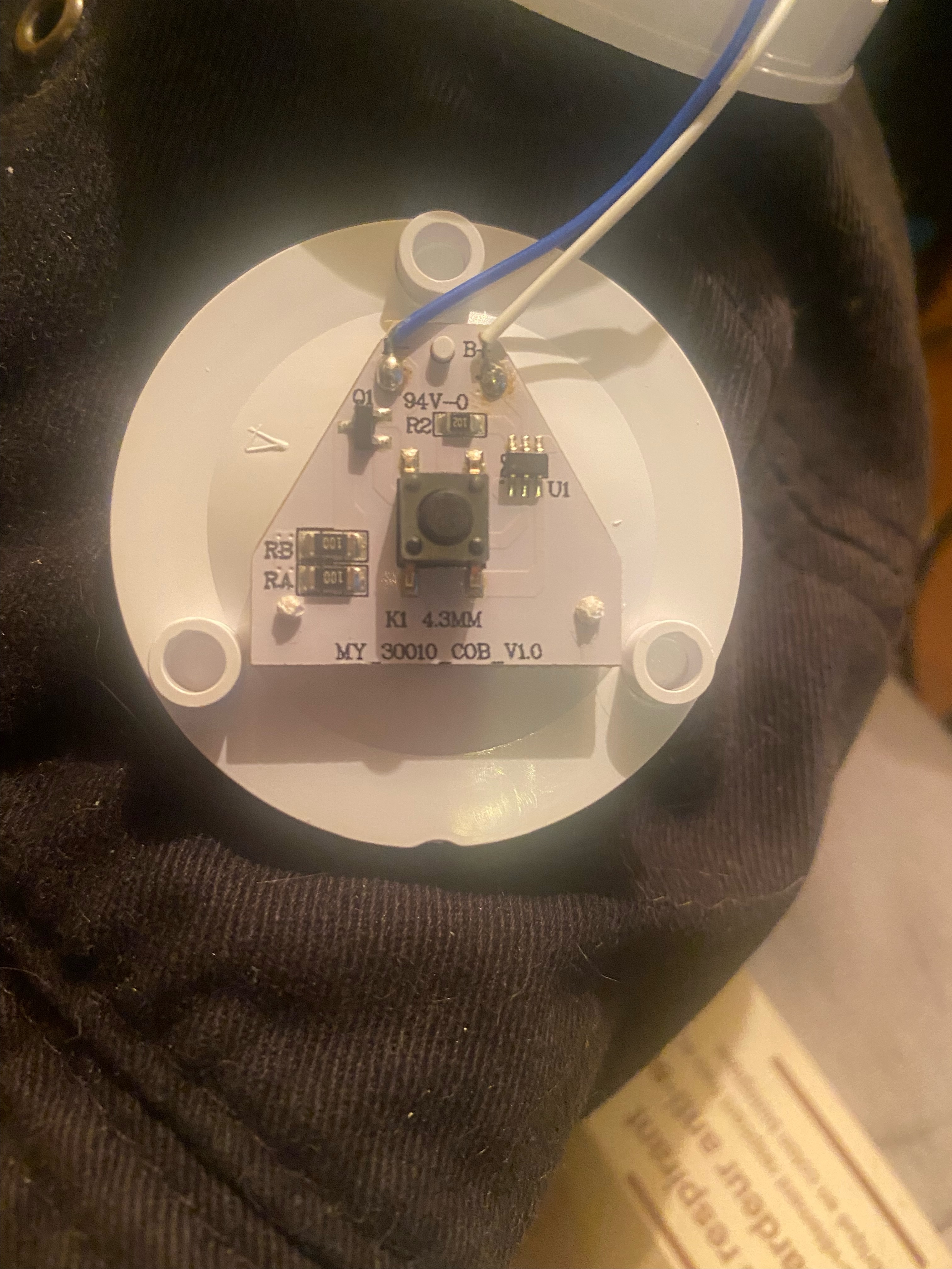
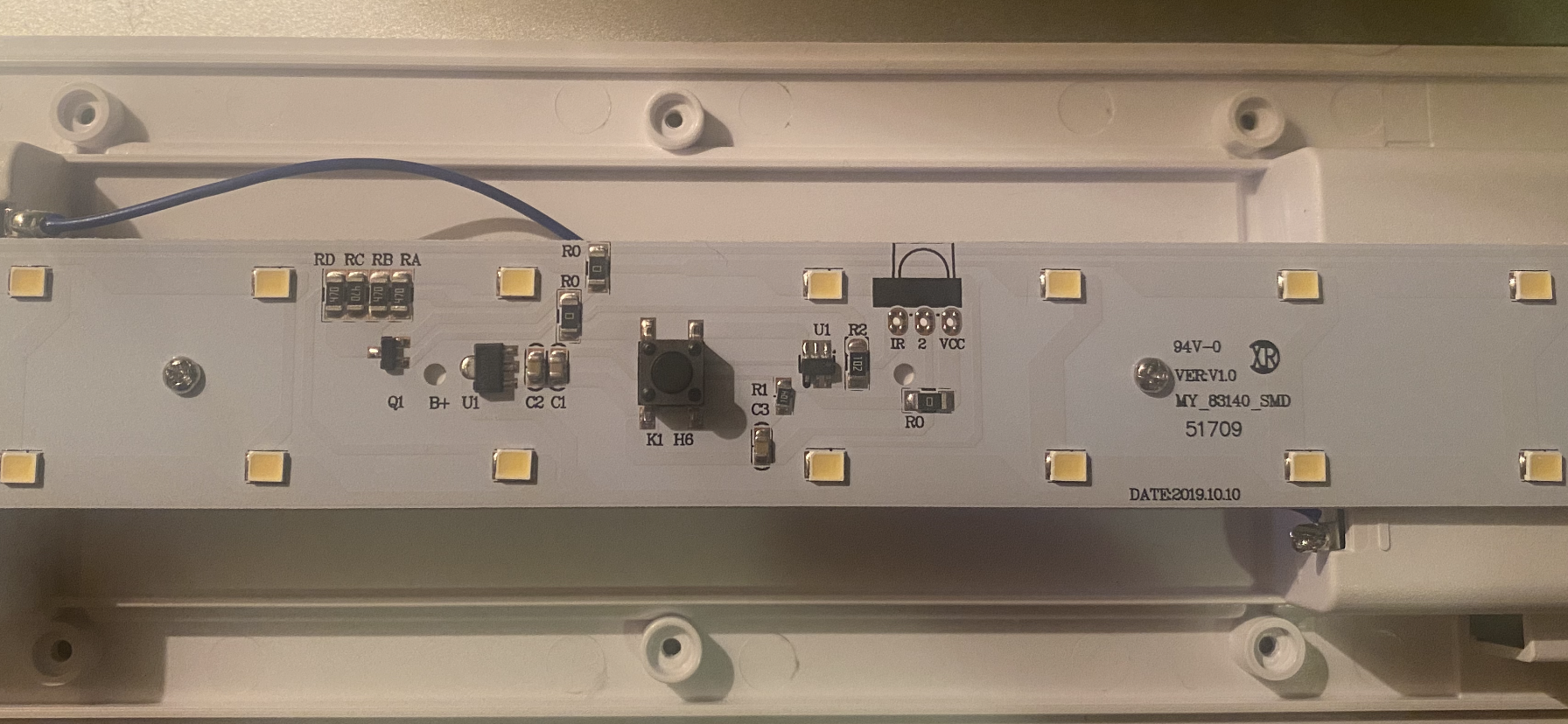
Hi all! I recently purchased some push-lights for my kitchen from my hardware store, and I stupidly didn't read the package that said that they shut off after 30 mins. This is super inconvenient in my dark kitchen, and I can't return them. I figured I might as well tinker with them, and any help would be greatly appreciated. The first picture is the small, round push-light (it was in a 3 pack, so I've got room for error with these), and the second picture was the even bigger disappointment because it's a larger strip light.
I found them online for reference here and here. It doesn't say they shut off in the description of these, but it says it in the user manual under "product guides and documents" for the rectangle light.
TL;DR: Help me bypass the "power saving" mode that shuts these off after 30 mins please!
'fraid that a little bit of effort producing the circuit diagram from the boards is really needed.
I think that it will show what has to be a microcontroller with an input pad going to the switch and another pad going to a base resistor for q1. Q1 switching power to LEDS via RA - D.
The long light looks to be fitted for a an IR receiver. With U1 near it possibly the decoder. As they show the thing stuck on a rafter presumably way out of reach - I suspect that 's a picture from the version with an IR controller. They have produced a cheaper version, without the sensor and re-used the photos.
Now, if that's how it is - I'd just remove the microcontroller and glue one of my favs upside down on the board and run wires from its pins to the relevant pads (removing the existing microcontroller). I haven't bought one recently, but 8 pin ones were costing me less than 50p... Having programmed the replacement with an added option to stay on.