Hackaday

880 readers
6 users here now

Fresh hacks every day

founded 1 year ago
MODERATORS
151


A favourite thing for the developers behind a complex software project is to embed an Easter egg: something unexpected that can be revealed only by those in the know. Apple certainly had their share of them in their early days, a practice brought to a close by Steve Jobs on his return to the company. One of the last Macs to contain one was the late 1990s beige G3, and while its existence has been know for years, until now nobody has decoded the means to display it on the Mac. Now [Doug Brown] has taken on the challenge.

The Easter egg is a JPEG file embedded in the ROM with portraits of the team, and it can’t be summoned with the keypress combinations used on earlier Macs. We’re taken on a whirlwind tour of ROM disassembly as he finds an unexpected string in the SCSI driver code. Eventually it’s found that formatting the RAM disk with the string as a volume name causes the JPEG to be saved into the disk, and any Mac user can come face to face with the dev team. It’s a joy reserved now for only a few collectors of vintage hardware, but still over a quarter century later, it’s fascinating to learn about. Meanwhile, this isn’t the first Mac easter egg to find its way here.


From Blog – Hackaday via this RSS feed

152


As humans we often think we have a pretty good handle on the basics of the way the world works, from an intuition about gravity good enough to let us walk around, play baseball, and land spacecraft on the moon, or an understanding of electricity good enough to build everything from indoor lighting to supercomputers. But zeroing in on any one phenomenon often shows a world full of mystery and surprise in an area we might think we would have fully understood by now. One such area is static electricity, and the way that it forms within certain materials shows that it can impart a kind of memory to them.

The video demonstrates a number of common ways of generating static electricity that most of us have experimented with in the past, whether on purpose or accidentally, from rubbing a balloon on one’s head and sticking it to the wall or accidentally shocking ourselves on a polyester blanket. It turns out that certain materials like these tend to charge themselves positively or negatively depending on what material they were rubbed against, but some researchers wondered what would happen if an object were rubbed against itself. It turns out that in this situation, small imperfections in the materials cause them to eventually self-order into a kind of hierarchy, and repeated charging of these otherwise identical objects only deepen this hierarchy over time essentially imparting a static electricity memory to them.

The effect of materials to gain or lose electrons in this way is known as the triboelectric effect, and there is an ordering of materials known as the triboelectric series that describes which materials are more likely to gain or lose electrons when brought into contact with other materials. The ability of some materials, like quartz in this experiment, to develop this memory is certainly an interesting consequence of an otherwise well-understood phenomenon, much like generating power for free from static electricity that’s always present within the atmosphere might surprise some as well.


From Blog – Hackaday via this RSS feed

153


Procedural generation is a big part of game design these days. Usually you generate your map, and [Fractal Philosophy] has decided to go one step further: using a procedurally-generated world from an older video, he is procedurally generating history by simulating the rise and fall of empires on that map in a video embedded below.

Now, lacking a proper theory of Psychohistory, [Fractal Philosophy] has chosen to go with what he admits is the simplest model he could find, one centered on the concept of “solidarity” and based on the work of [Peter Turchin], a Russian-American thinker. “Solidarity” in the population holds the Empire together; external pressures increase it, and internal pressures decrease it. This leads to an obvious cellular automation type system (like Conway’s Game of Life), where cells are evaluated based on their nearest neighbors: the number of nearest neighbors in the empire goes into a function that gives the probability of increasing or decreasing the solidarity score each “turn”. (Probability, in order to preserve some randomness.) The “strength” of the Empire is given by the sum of the solidarity scores in every cell.

Each turn, Empires clash, with the the local solidarity, sum strength, and distance from Imperial center going into determining who gains or loses territory. It is a simple model; you can judge from the video how well it captures the ebb and flow of history, but we think it did surprisingly well all things considered. The extra 40-minute video of the model running is oddly hypnotic, too.

3D model of an Alpaca next to a LlamaIn v2 of the model, one of these fluffy creatures will betray you.

After a dive into more academic support for the main idea, and a segue into game theory and economics, a slight complication is introduced later in the video, dividing each cell into two populations: “cooperators” or “selfish” individuals.

This allows for modeling of internal conflicts between the two groups. This hitch gives a very similar looking map at the end of its run, although has an odd quirk that it automatically starts with a space-filling empire across the whole map that quickly disintegrates.

Unfortunately, the model not open-source, but the ideas are discussed in enough detail that one could probably produce a very similar algorithm in an afternoon. For those really interested, [Fractal Philosophy] does offer a one-time purchase through his Patreon. It also includes the map-generating model from his last video.

We’re much more likely to talk about simulating circuits, or feature projects that use fluid simulations here at Hackaday, but this hack of a history model


From Blog – Hackaday via this RSS feed

154


[Claywoven] mostly prints with ceramics, although he does produce plastic inserts for functional parts in his designs. The ceramic parts have an interesting texture, and he wondered if the same techniques could work with plastics, too. It turns out it can, as you can see in the video below.

Ceramic printing, of course, doesn’t get solid right away, so the plastic can actually take more dramatic patterns than the ceramic. The workflow starts with Blender and winds up with a standard printer.

The example prints are lamps, although you could probably do a lot with this technique. You can select where the texturing occurs, which is important in this case to allow working threads to avoid having texture.

You will need a Blender plugin to get similar results. The target printer was a Bambu, but there’s no reason this wouldn’t work with any FDM printer.

We admire this kind of artistic print. We’ve talked before about how you can use any texture to get interesting results. If you need help getting started with Blender, our tutorial is one place to start.


From Blog – Hackaday via this RSS feed

155


We haven’t seen any projects from serial experimenter [Les Wright] for quite a while, and honestly, we were getting a little worried about that. Turns out we needn’t have fretted, as [Les] was deep into this exploration of the Pockels Effect, with pretty cool results.

If you’ll recall, [Les]’s last appearance on these pages concerned the automated creation of huge, perfect crystals of KDP, or potassium dihydrogen phosphate. KDP crystals have many interesting properties, but the focus here is on their ability to modulate light when an electrical charge is applied to the crystal. That’s the Pockels Effect, and while there are commercially available Pockels cells available for use mainly as optical switches, where’s the sport in buying when you can build?

As with most of [Les]’s projects, there are hacks galore here, but the hackiest is probably the homemade diamond wire saw. The fragile KDP crystals need to be cut before use, and rather than risk his beauties to a bandsaw or angle grinder, [Les] threw together a rig using a stepper motor and some cheap diamond-encrusted wire. The motor moves the diamond wire up and down while a weight forces the crystal against it on a moving sled. Brilliant!

The cut crystals are then polished before being mounted between conductive ITO glass and connected to a high-voltage supply. The video below shows the beautiful polarization changes induced by the electric field, as well as demonstrating how well the Pockels cell acts as an optical switch. It’s kind of neat to see a clear crystal completely block a laser just by flipping a switch.

Nice work, [Les], and great to have you back.


From Blog – Hackaday via this RSS feed

156


This week Jonathan chats with Davide Bettio and Paul Guyot about AtomVM! Why Elixir on embedded? And how!? And what is a full stack Elixir developer, anyways? Watch to find out!

https://atomvm.org/https://github.com/atomvm/AtomVMhttps://popcorn.swmansion.com/https://www.kickstarter.com/projects/multiplie/la-machine

Did you know you can watch the live recording of the show right on our YouTube Channel? Have someone you’d like us to interview? Let us know, or contact the guest and have them contact us! Take a look at the schedule here.

Direct Download in DRM-free MP3.

If you’d rather read along, here’s the transcript for this week’s episode.

Places to follow the FLOSS Weekly Podcast:

SpotifyRSS

Theme music: “Newer Wave” Kevin MacLeod (incompetech.com)

Licensed under Creative Commons: By Attribution 4.0 License


From Blog – Hackaday via this RSS feed

157


If you ever look at projects in an old magazine and compare them to today’s electronic projects, there’s at least one thing that will stand out. Most projects in “the old days” looked like something you built in your garage. Today, if you want to make something that rivals a commercial product, it isn’t nearly as big of a problem.

Dynamic diode tester from Popular Electronics (July 1970)

For example, consider the picture of this project from Popular Electronics in 1970. It actually looks pretty nice for a hobby project, but you’d never expect to see it on a store shelf.

Even worse, the amount of effort required to make it look even this good was probably more than you’d expect. The box was a standard case, and drilling holes in a panel would be about the same as it is today, but you were probably less likely to have a drill press in 1970.

But check out the lettering! This is a time before inkjet and laser printers. I’d guess these are probably “rub on” letters, although there are other options. Most projects that didn’t show up in magazines probably had Dymo embossed lettering tape or handwritten labels.

Another project from the same issue of Popular Electronics. Nice lettering, but the aluminum box is a dead giveaway

Of course, even as now, sometimes you just make a junky looking project, but to make a showpiece, you had to spend way more time back then to get a far less professional result.

You notice the boxes are all “stock,” so that was part of it. If you were very handy, you might make your own metal case or, more likely, a wooden case. But that usually gave away its homemade nature, too. Very few commercial items come in a wooden box, and those that do are in fine furniture, not some slap-together box with a coat of paint.

The Inside Story

A Dymo label gun you could buy at Radio Shack

The insides were also a giveaway. While PC boards were not unknown, they were very expensive to have produced commercially. Sure, you could make your own, but it wasn’t as easy as it is now. You probably hand-drew your pattern on a copper board or maybe on a transparency if you were photo etching. Remember, no nice computer printers yet, at least not in your home.

So, most home projects were handwired or maybe wirewrapped. Not that there isn’t a certain aesthetic to that. Beautiful handwiring can be almost an art form. But it hardly looks like a commercial product.

Kits

The best way to get something that looked more or less professional was to get a kit from Heathkit, Allied, or any of the other kit makers. They usually had nice cases with lettering. But building a kit doesn’t feel the same as making something totally from scratch.

Sure, you could modify the kit, and many did. But still not quite the same thing. Besides, not all kits looked any better than your own projects.

The Tao

Of course, maybe we shouldn’t emulate commercial products. Some of the appeal of a homemade product is that it looks homemade. It is like the Tao of Programming notes about software development:

3.3 There was once a programmer who was attached to the court of the warlord of Wu. The warlord asked the programmer: “Which is easier to design: an accounting package or an operating system?”

“An operating system,” replied the programmer.

The warlord uttered an exclamation of disbelief. “Surely an accounting package is trivial next to the complexity of an operating system,” he said.

“Not so,” said the programmer, “When designing an accounting package, the programmer operates as a mediator between people having different ideas: how it must operate, how its reports must appear, and how it must conform to the tax laws. By contrast, an operating system is not limited by outside appearances. When designing an operating system, the programmer seeks the simplest harmony between machine and ideas. This is why an operating system is easier to design.”

Commercial gear has to conform to standards and interface with generic things. Bespoke projects can “seek the simplest harmony between machine and ideas.”

Then again, if you are trying to make something to sell on Tindie, or as a prototype, maybe commercial appeal is a good thing. But if you are just building for yourself, maybe leaning into the homebrew look is a better choice. Who would want to mess with a beautiful wooden arcade cabinet, for example? Or this unique turntable?

Let us know how you feel about it in the comments.


From Blog – Hackaday via this RSS feed

158


If you need a seven-segment display for a project, you could just grab some LED units off the shelf. Or you could build something big and electromechanical out of Lego. That’s precisely what [upir] did, with attractive results.

The build relies on Lego Technic parts, with numbers displayed by pushing small black axles through a large yellow faceplate. This creates a clear and easy to read display thanks to the high contrast. Each segment is made up of seven axles that move as a single unit, driven by a gear rack to extend and retract as needed. By extending and retracting the various segments in turn, it’s possible to display all the usual figures you’d expect of a seven-segment design.

It’s worth noting, though, that not everything in this build is Lego. The motors that drive the segments back and forth are third-party components. They’re Geekservo motors, which basically act as Lego-mountable servos you can drive with the electronics of your choice. They’re paired with an eight-channel servo driver board which controls each segment individually. Ideally, though, we’d see this display paired with a microcontroller for more flexibility. [upir] leaves that as an exercise for the viewer for now, with future plans to drive it with an Arduino Uno.

Design files are on Github for the curious. We’ve featured some similar work before, too, because you really can build anything out of Lego. Video after the break.


From Blog – Hackaday via this RSS feed

159


As the Industrial Age took the world by storm, city centers became burgeoning hubs of commerce and activity. New offices and apartments were built higher and higher as density increased and skylines grew ever upwards. One could live and work at height, but this created a simple inconvenience—if you wanted to send any mail, you had to go all the way down to ground level.

In true American fashion, this minor inconvenience would not be allowed to stand. A simple invention would solve the problem, only to later fall out of vogue as technology and safety standards moved on. Today, we explore the rise and fall of the humble mail chute.

Going Down

Born in 1848 in Albany, New York, James Goold Cutler would come to build his life in the state. He lived and worked in the growing state, and as an architect, he soon came to identify an obvious problem. For those occupying higher floors in taller buildings, the simple act of sending a piece of mail could quickly become a tedious exercise. One would have to make their way all the way to a street level post box, which grew increasingly tiresome as buildings grew ever taller.

Cutler’s original patent for the mail chute. Note element G – a hand guard that prevented people from reaching into the chute to grab mail falling from above. Security of the mail was a key part of the design. Credit: US Patent, public domain

Cutler saw that there was an obvious solution—install a vertical chute running through the building’s core, add mail slots on each floor, and let gravity do the work. It then became as simple as dropping a letter in, and down it would go to a collection box at the bottom, where postal workers could retrieve it during their regular rounds. Cutler filed a patent for this simple design in 1883. He was sure to include a critical security feature—a hand guard behind each floor’s mail chute. This was intended to stop those on lower levels reaching into the chute to steal the mail passing by from above. Installations in taller buildings were also to be fitted with an “elastic cushion” in the bottom to “prevent injury to the mail” from higher drop heights.

A Cutler Receiving Box that was built in 1920. This box would have lived at the bottom of a long mail chute, with the large door for access by postal workers. The brass design is typical of the era. Credit: National Postal Museum, CC0

One year later, the first installation went live in the Elwood Building, built in Rochester, New York to Cutler’s own design. The chute proved fit for purpose in the seven-story building, but there was a problem. The collection box at the bottom of Cutler’s chute was seen by the postal authorities as a mailbox. Federal mail laws were taken quite seriously, then as now, and they stated that mailboxes could only be installed in public buildings such as hotels, railway stations, or government facilities. The Elwood was a private building, and thus postal carriers refused to service the collection box.

It consists of a chute running down through each story to a mail box on the ground floor, where the postman can come and take up the entire mail of the tenants of the building. A patent was easily secured, for nobody else had before thought of nailing four boards together and calling it a great thing.

Letters could be dropped in the apertures on the fourth and fifth floors and they always fell down to the ground floor all right, but there they stated. The postman would not touch them. The trouble with the mail chute was the law which says that mail boxes shall be put only in Government and public buildings.

The Sun, New York, 20 Dec 1886

Cutler’s brilliantly simple invention seemed dashed at the first hurdle. However, rationality soon prevailed. Postal laws were revised in 1893, and mail chutes were placed under the authority of the US Post Office Department. This had important security implications. Only post-office approved technicians would be allowed to clear mail clogs and repair and maintain the chutes, to ensure the safety and integrity of the mail.

The Cutler Mail chutes are easy to spot at the Empire State Building. Credit: Teknorat, CC BY-SA 2.0

With the legal issues solved, the mail chute soared in popularity. As skyscrapers became ever more popular at the dawn of the 20th century, so did the mail chute, with over 1,600 installed by 1905. The Cutler Manufacturing Company had been the sole manufacturer reaping the benefits of this boom up until 1904, when the US Post Office looked to permit competition in the market. However, Cutler’s patent held fast, with his company merging with some rivals and suing others to dominate the market. The company also began selling around the world, with London’s famous Savoy Hotel installing a Cutler chute in 1904. By 1961, the company held 70 percent of the mail chute market, despite Cutler’s passing and the expiry of the patent many years prior.

The value of the mail chute was obvious, but its success was not to last. Many companies began implementing dedicated mail rooms, which provided both delivery and pickup services across the floors of larger buildings. This required more manual handling, but avoided issues with clogs and lost mail and better suited bigger operations. As postal volumes increased, the chutes became seen as a liability more than a convenience when it came to important correspondence. Larger oversized envelopes proved a particular problem, with most chutes only designed to handle smaller envelopes. A particularly famous event in 1986 saw 40,000 pieces of mail stuck in a monster jam at the McGraw-Hill building, which took 23 mailbags to clear. It wasn’t unusual for a piece of mail to get lost in a chute, only to turn up many decades later, undelivered.

An active mail chute in the Law Building in Akron, Ohio. The chute is still regularly visited by postal workers for pickup. Credit: Cards84664, CC BY SA 4.0 Mail chutes were often given fine, detailed designs befitting the building they were installed in. This example is from the Fitzsimons Army Medical Center in Colorado. Credit: Mikepascoe, CC BY SA 4.0

The final death knell for the mail chute, though, was a safety matter. Come 1997, the National Fire Protection Association outright banned the installation of new mail chutes in new and existing buildings. The reasoning was simple. A mail chute was a single continuous cavity between many floors of a building, which could easily spread smoke and even flames, just like a chimney.

Despite falling out of favor, however, some functional mail chutes do persist to this day. Real examples can still be spotted in places like the Empire State Building and New York’s Grand Central station. Whether in use or deactivated, many still remain in older buildings as a visible piece of mail history.

Better building design standards and the unstoppable rise of email mean that the mail chute is ultimately a piece of history rather than a convenience of our modern age. Still, it’s neat to think that once upon a time, you could climb to the very highest floors of an office building and drop your important letters all the way to the bottom without having to use the elevator or stairs.

Collage of mail chutes from Wikimedia Commons, Mark Turnauckas, and Britta Gustafson.


From Blog – Hackaday via this RSS feed

160


Kumiko is a form of Japanese woodworking that uses small cuts of wood (probably offcuts) to produce artful designs. It’s the kind of thing that takes zen-like patience to assemble, and years to master– and who has time for that? [Paper View] likes the style of kumiko, but when all you have is a 3D printer, everything is extruded plastic.

His video, embedded below, focuses mostly on the large tiled piece and the clever design required to avoid more than the unavoidable unsightly seams without excessive post processing. (Who has time for that?) The key is a series of top pieces to hide the edges where the seams come together. The link above, however, gives something more interesting, even if it is on Makerworld.

[Paper View] has created a kumiko-style (out of respect for the craftspeople who make the real thing, we won’t call this “kumiko”) panel generator, that allows one to create custom-sized frames to print either in one piece, or to assemble as in the video. We haven’t looked at MakerWorld’s Parametric Model Maker before, but this tool seems to make full use of its capabilities (to the point of occasionally timing out). It looks like this is a wrapper for OpenScad (just like Thingiverse used to do with Customizer) so there might be a chance if enough of us comment on the video [Paper View] can be convinced to release the scad files on a more open platform.

We’ve featured kumiko before, like this wood-epoxy guitar, but for ultimate irony points, you need to see this metal kumiko pattern made out of nails. (True kumiko cannot use nails, you see.)

Thanks to [Hari Wiguna] for the tip, and please keep them coming!


From Blog – Hackaday via this RSS feed

161


Can a 3D Minecraft implementation be done entirely in CSS and HTML, without a single line of JavaScript in sight? The answer is yes!

True, this small clone is limited to playing with blocks in a world that measures only 9x9x9, but the fact that [Benjamin Aster] managed it at all using only CSS and pure HTML is a fantastic achievement. As far as proofs of concept go, it’s a pretty clever one.

The project consists of roughly 40,000 lines of HTML radio buttons and labels, combined with fewer than 500 lines of CSS where the real work is done. In a short thread on X [Benjamin] explains that each block in the 9x9x9 world is defined with the help of tens of thousands of and elements to track block types and faces, and CSS uses that as a type of display filter. Clicking a block is clicking a label, and changing a block type (“air” or no block is considered a type of block) switches which labels are visible to the user.

Viewing in 3D is implemented via CSS animations which apply transforms to what is displayed. Clicking a control starts and stops the animation, resulting in a view change. It’s a lot of atypical functionality for plain HTML and CSS, showing what is possible with a bit of out-of-the-box thinking.

[Simon Willison] has a more in-depth analysis of CSS-Minecraft and how it works, and the code is on GitHub if you want a closer look.

Once you’re done checking that out and hungry for more cleverness, don’t miss Minecraft in COBOL and Minecraft Running in… Minecraft.


From Blog – Hackaday via this RSS feed

162


Two images side by side. One shows a laptop opened to a map view with a vehicle model showing a vehicles location. A transparent overlay shows various blue-ish buttons for sending commands to the vehicle. The image on the right is of the interior of a Nissan Leaf. Visible are the very edge of the steering wheel, the center dash including the infotainment display, vents, and shifter, and part of the right side of the dash. Passenger and driver legs are just barely visible at the bottom of the image.

As cars increasingly become computers on wheels, the attack surface for digital malfeasance increases. [PCAutomotive] has shared its exploit for turning the 2020 Nissan Leaf into 1600 kg RC car. [PDF via Electrek]

Starting with some scavenged infotainment systems and wiring harnesses, the group built test benches able to tear into vulnerabilities in the system. An exploit was found in the infotainment system’s Bluetooth implementation, and they used this to gain access to the rest of the system. By jamming the 2.4 GHz spectrum, the attacker can nudge the driver to open the Bluetooth connection menu on the vehicle to see why their phone isn’t connecting. If this menu is open, pairing can be completed without further user interaction.

Once the attacker gains access, they can control many vehicle functions, such as steering, braking, windshield wipers, and mirrors. It also allows remote monitoring of the vehicle through GPS and recording audio in the cabin. The vulnerabilities were all disclosed to Nissan before public release, so be sure to keep your infotainment system up-to-date!

If this feels familiar, we featured a similar hack on Tesla infotainment systems. If you’d like to hack your Leaf for the better, we’ve also covered how to fix some of the vehicle’s charging flaws, but we can’t help you with the loss of app support for early models.


From Blog – Hackaday via this RSS feed

163


A map of the United States showing a series of interconnected lines in white, red, orange, yellow, and green to denote fiber optic and electrical transmission lines. Dots of white, orange, and yellow denote the location of the data centers relative to nearby metropolitan centers.

Spending time as wee hackers perusing the family atlas taught us an appreciation for a good map, and [Billy Roberts], a cartographer at NREL, has served up a doozy with a map of the data center infrastructure in the United States. [via LinkedIn]

Fiber optic lines, electrical transmission capacity, and the data centers themselves are all here. Each data center is a dot with its size indicating how power hungry it is and its approximate location relative to nearby metropolitan areas. Color coding of these dots also helps us understand if the data center is already in operation (yellow), under construction (orange), or proposed (white).

Also of interest to renewable energy nerds would be the presence of some high voltage DC transmission lines on the map which may be the future of electrical transmission. As the exact location of fiber optic lines and other data making up the map are either proprietary, sensitive, or both, the map is only available as a static image.

If you’re itching to learn more about maps, how about exploring why they don’t quite match reality, how to bring OpenStreetMap data into Minecraft, or see how the live map in a 1960s airliner worked.


From Blog – Hackaday via this RSS feed

164


Leica’s film cameras were hugely popular in the 20th century, and remain so with collectors to this day. [Michael Suguitan] has previously had great success converting his classic Leica into a digital one, and now he’s taken the project even further.

[Michael’s] previous work saw him create a so-called “digital back” for the Leica M2. He fitted the classic camera with a Raspberry Pi Zero and a small imaging sensor to effectively turn it into a digital camera, creating what he called the LeicaMPi. Since then, [Michael] has made a range of upgrades to create what he calls the LeicaM2Pi.

The upgrades start with the image sensor. This time around, instead of using a generic Raspberry Pi camera, he’s gone with the fancier ArduCam OwlSight sensor. Boasting a mighty 64 megapixels, it’s still largely compatible with all the same software tools as the first-party cameras, making it both capable and easy to use. With a  crop factor of 3.7x, the camera’s Voigtlander 12mm lens has a much more useful field of view.

Unlike [Michael’s] previous setup, there was also no need to remove the camera’s IR filter to clear the shutter mechanism. This means the new camera is capable of taking natural color photos during the day.  [Michael] also added a flash this time around, controlled by the GPIOs of the Raspberry Pi Zero. The camera also features a much tidier onboard battery via the PiSugar module, which can be easily recharged with a USB-C cable.

If you’ve ever thought about converting an old-school film camera into a digital shooter, [Michael’s] work might serve as a great jumping off point. We’ve seen it done with DSLRs, before, too! Video after the break.

[Thanks to Stephen Walters for the tip!]


From Blog – Hackaday via this RSS feed

165


The choice between hardware and software for electronics projects is generally a straighforward one. For simple tasks we might build dedicated hardware circuits out of discrete components for reliability and low cost, but for more complex tasks it could be easier and cheaper to program a general purpose microcontroller than to build the equivalent circuit in hardware. Every now and then we’ll see a project that blurs the lines between these two choices like this Pong game built entirely out of discrete components.

The project begins with a somewhat low-quality image of the original Pong circuit found online, which [atkelar] used to model the circuit in KiCad. Because the image wasn’t the highest resolution some guesses needed to be made, but it was enough to eventually produce a PCB and bill of material. From there [atkelar] could start piecing the circuit together, starting with the clock and eventually working through all the other components of the game, troubleshooting as he went. There were of course a few bugs to work out, as with any hardware project of this complexity, but in the end the bugs in the first PCB were found and used to create a second PCB with the issues solved.

With a wood, and metal case rounding out the build to showcase the circuit, nothing is left but to plug this in to a monitor and start playing this recreation of the first mass-produced video game ever made. Pong is a fairly popular build since, at least compared to modern games, it’s simple enough to build completely in hardware. This version from a few years ago goes even beyond [atkelar]’s integrated circuit design and instead built a recreation out of transistors and diodes directly.

Thanks to [irdc] for the tip!


From Blog – Hackaday via this RSS feed

166


If you do anything with electronics or electricity, it is a good bet you have a multimeter. Even the cheapest meter today would have been an incredible piece of lab gear not long ago and, often, meters today are lighter and have more features than the old Radio Shack meters we grew up with. But then there are bench meters. [Learn Electronics Repair] reviews an OWON XDM1241 meter, and you have to wonder if it is better than just a decent handheld device. Check out the video below and see what you think.

Some of the advantage of a bench meter is just convenience. They stay in one place and often have a bigger display than a handheld. Of course, these days, the bench meter isn’t much better than a handheld anyway. In fact, one version of this meter even has a battery, if you want to carry it around.

Traditionally, bench meters had more digits and counts, although that’s not always true anymore. This meter has 55,000 counts with four and a half digits. It has a large LCD, can connect to a PC, and measures frequency, temperature, and capacitance.

Our bench meters usually have four-wire resistance measurement, but that does not seem to be the case for these meters. It does, however, take frequent measurements, which is a plus when ringing out continuity, for example.

The meter isn’t perfect, but if you just want a bench meter, it works well enough. If we had the space, we might opt for a bigger old surplus Fluke or similar. But if you want something new or you are short on space, this might be fine.

If you want to know what you are missing by not having four-wire measurements, we can help you with that. If you get any of these cheaper meters, we urge you to upgrade your probes immediately.


From Blog – Hackaday via this RSS feed

167


When you really love your pawed, feathered, or scaled friends, you build projects for them. (Well, anyway, that’s what’s happened to us.) For the 2025 Pet Hacks Challenge, we asked you to share your favorite pet-related hacks, and you all delivered. So without further ado, here are our favorites, as well as the picks-of-the-litter that qualified for three $150 DigiKey gift certificates. Spoiler alert: it was a clean sweep for team cat.

The Top Three

[Andrea Favero]’s CAT AT THE DOOR project (his caps, not ours) packs more tech than strictly necessary, and our judges loved it. When the cat approaches, a radar detects it, a BLE collar identifies the particular cat, and a LoRA radio notifies the human on a beautiful e-ink display with a sufficiently loud beeper. Your job, then, is to open the door. This project has standout build instructions, and even if you’re a dog person, you’ll want to read them if you’re using any of these technologies in a build of your own.

Foxy and Layla are two cats on two different diets. One has prescription food that unfortunately isn’t as tasty as the regular stuff, but that doesn’t mean she can just mompf up the other cat’s chow. The solution? Computer vision! [Joe Mattioni]’s Cat Bowl Monitor hacks a commercial cat feeder to operate via an Android app running on an old cell phone. [Joe] trained the image recognition algorithm specifically on his two cats, which helps reliability greatly. Like the previous winner, the documentation is great, and it’s a sweet application of real-time image classification and a nice reuse of an oldish cellphone. Kudos!

And finally, [rkramer]’s Cat Valve is a one-way cat airlock. Since “Bad Kitty” likes to go out hunting at night, and [rkramer] doesn’t like having live trophies continually brought back into the house, a sliding door lets the cat out, but then closes behind. A webcam and a Raspberry Pi lets the human decide if the cat gets to come back in or not, relying on HI (Human Intelligence) for the image processing. This isn’t inhumane: the cat isn’t stuck outside, but merely in the cellar. No mention of how [rkramer] gets the traumatized rats out of his cellar, but we imagine there’ll be a hack for that as well.

Congrats to you three! We’ll be getting in touch with you soon to get your $150 DigiKey spending spree.

Honorable Mentions

The “Pet Safety” honorable mention category was created to honor those hacks that help promote pet health and safety. Nothing fit that bill as well as [donutsorelse]’s Chicken Guardian, which uses computer vision to detect various predators and scare them away with a loud voice recording. (We’re not sure if that’s entertaining or effective.) [Saren Tasciyan]’s Dog bed is also a dog scale that does just what it says, and we imagine that it’s a huge quality of life improvement for both the Bernese and her owners. And finally, [methodicalmaker_]’s IoT Cat Treat Dispenser + Treadmill for Weight Loss is a paradox: rewarding a cat with food for getting on a treadmill to lose weight. Time will tell if the dosages can be calibrated just right.

In the “Home Alone” category, we wanted to see remote pet-care ideas. Of course, there was a vacation fish feeder, in the form of [Coders Cafe]’s Aquassist, which we really liked for the phone app – it’s a simple build that looks great. Further from the beaten path, [kasik]’s TinyML meets dog training is a cool experiment in machine learning that also feeds and distracts the dog from barking at the door, even when [kasik] is out.

“Playful Pets” was for the goofy, fun, pet hacks, and the hamsters have won it. [Giulio Pons] brought us Ruby’s Connected Hamster Wheel, which tracked his hamster’s mileage on the wheel at night for two years running, and [Roni Bandini]’s Wall Street hamster project lets Milstein buy and sell stonks. Hilarious, and hopefully not too financially painful.

And finally, the “Cyborg Pets” category just has to go to Fytó, which basically gamifies taking care of a plant. There was intense debate about whether a plant could be a pet, but what’s more cyborg than a living Tamagotchi?

Thanks!

Thanks to everyone who entered! It was awesome to see your efforts on behalf of our animal friends. And if you didn’t get to enter because you just don’t have a pet, check back in with us on Thursday, when our next challenge begins.


From Blog – Hackaday via this RSS feed

168


If you’re designing a new jet-powered airplane, one of the design considerations is the number of jet engines you will put on it. Over the course of history we have seen everywhere from a single engine, all the way up to four and beyond, with today airliners usually having two engines aside from the Boeing 747 and Airbus A380 has been largely phased out. Yet for a long time airliners featured three engines, which raises the question of why this configuration has mostly vanished now. This is the topic of a recent YouTube video by [Plane Curious], embedded below.

The Boeing 727, DC-10 and L-1011 TriStar are probably among the most well-known trijets, all being unveiled around the same time. The main reason for this was actually regulatory, as twin-engine designs were thought to be too unsafe for long flights across oceans, while quad-jet designs were too fuel-hungry. This remained the situation until newer jet engine designs that were more reliable and powerful, leading to new safety standards  (ETOPS) that allowed twinjets to fly these longer routes as well. Consequently, the last passenger trijet – an MD-11 KLM flight – touched down in 2014.

Along with the engineering and maintenance challenges that come with having a tail-mounted jet engine, the era of trijets seem to have firmly come to an end, at least for commercial airliners.


From Blog – Hackaday via this RSS feed

169


It’s an inconvenient fact that most of Earth’s largesse of useful minerals is locked up in, under, and around a lot of rock. Our little world condensed out of the remnants of stars whose death throes cooked up almost every element in the periodic table, and in the intervening billions of years, those elements have sorted themselves out into deposits that range from the easily accessed, lying-about-on-the-ground types to those buried deep in the crust, or worse yet, those that are distributed so sparsely within a mineral matrix that it takes harvesting megatonnes of material to find just a few kilos of the stuff.

Whatever the substance of our desires, and no matter how it is associated with the rocks and minerals below our feet, almost every mining and refining effort starts with wresting vast quantities of rock from the Earth’s crust. And the easiest, cheapest, and fastest way to do that most often involves blasting. In a very real way, explosives make the world work, for without them, the minerals we need to do almost anything would be prohibitively expensive to produce, if it were possible at all. And understanding the chemistry, physics, and engineering behind blasting operations is key to understanding almost everything about Mining and Refining.

First, We Drill

For almost all of the time that we’ve been mining minerals, making big rocks into smaller rocks has been the work of strong backs and arms supplemented by the mechanical advantage of tools like picks, pry bars, and shovels. The historical record shows that early miners tried to reduce this effort with clever applications of low-energy physics, such as jamming wooden plugs into holes in the rocks and soaking them with liquid to swell the wood and exert enough force to fracture the rock, or by heating the rock with bonfires and then flooding with cold water to create thermal stress fractures. These methods, while effective, only traded effort for time, and only worked for certain types of rock.

Mining productivity got a much-needed boost in 1627 with the first recorded use of gunpowder for blasting at a gold mine in what is now Slovakia. Boreholes were stuffed with powder that was ignited by a fuse made from a powder-filled reed. The result was a pile of rubble that would have taken weeks to produce by hand, and while the speed with which the explosion achieved that result was probably much welcomed by the miners, in reality, it only shifted their efforts to drilling the boreholes, which generally took a five-man crew using sledgehammers and striker bars to pound deep holes into the rock. Replacing that manual effort with mechanical drilling was the next big advance, but it would have to wait until the Industrial Revolution harnessed the power of steam to run drills capable of boring deep holes in rock quickly and with much smaller crews.

The basic principles of rock drilling developed in the 19th century, such as rapidly spinning a hardened steel bit while exerting tremendous down-pressure and high-impulse percussion, remain applicable today, although with advancements like synthetic diamond tooling and better methods of power transmission. Modern drills for open-cast mining fall into two broad categories: overburden drills, which typically drill straight down or at a slight angle to vertical and can drill large-diameter holes over 100 meters deep, and quarry drills, which are smaller and more maneuverable rigs that can drill at any angle, even horizontally. Most drill rigs are track-driven for greater mobility over rubble-strewn surfaces, and are equipped with soundproofed, air-conditioned cabs with safety cages to protect the operator. Automation is a big part of modern rigs, with automatic leveling systems, tool changers that can select the proper bit for the rock type, and fully automated drill chain handling, including addition of drill rod to push the bit deeper into the rock. Many drill rigs even have semi-autonomous operation, where a single operator can control a fleet of rigs from a single remote control console.

Proper Prior Planning

While the use of explosives seems brutally chaotic and indiscriminate, it’s really the exact opposite. Each of the so-called “shots” in a blasting operation is a carefully controlled, highly engineered event designed to move material in a specific direction with the desired degree of fracturing, all while ensuring the safety of the miners and the facility.

To accomplish this, a blasting plan is put together by a mining engineer. The blasting plan takes into account the mechanical characteristics of the rock, the location and direction of any pre-existing fractures or faults, and proximity to any structures or hazards. Engineers also need to account for the equipment used for mucking, which is the process of removing blasted material for further processing. For instance, a wheeled loader operating on the same level, or bench, that the blasting took place on needs a different size and shape of rubble pile than an excavator or dragline operating from the bench above. The capabilities of the rock crushing machinery that’s going to be used to process the rubble also have to be accounted for in the blasting plan.

Most blasting plans define a matrix of drill holes with very specific spacing, generally with long rows and short columns. The drill plan specifies the diameter of each hole along with its depth, which usually goes a little beyond the distance to the next bench down. The mining engineer also specifies a stem height for the hole, which leaves room on top of the explosives to backfill the hole with drill tailings or gravel.

Prills and Oil

Once the drill holes are complete and inspected, charging the holes with explosives can begin. The type of blasting agents to be used is determined by the blasting plan, but in most cases, the agent of choice is ANFO, or ammonium nitrate and fuel oil. The ammonium nitrate, which contains 60% oxygen by weight, serves as an oxidizer for the combustion of the long-chain alkanes in the fuel oil. The ideal mix is 94% ammonium nitrate to 6% fuel oil.

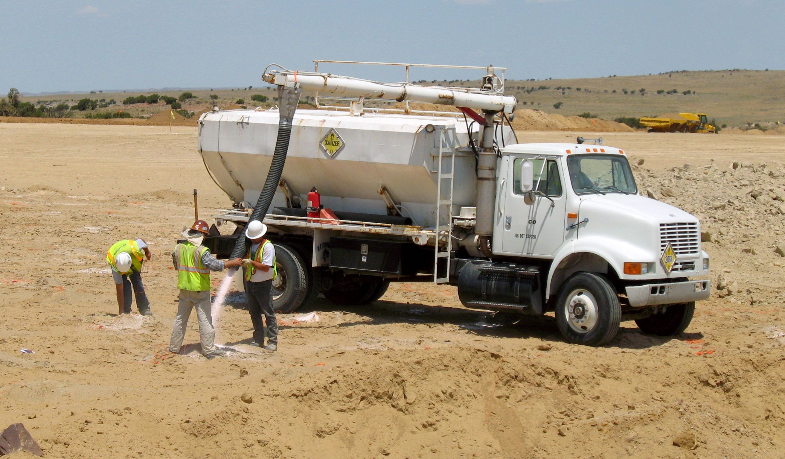
Filling holes with ammonium nitrate at a blasting site. Hopper trucks like this are often used to carry prilled ammonium nitrate. Some trucks also have a tank for the fuel oil that’s added to the ammonium nitrate to make ANFO. Credit: Old Bear Photo, via Adobe Stock.

How the ANFO is added to the hole depends on conditions. For holes where groundwater is not a problem, ammonium nitrate in the form of small porous beads or prills, is poured down the hole and lightly tamped to remove any voids or air spaces before the correct amount of fuel oil is added. For wet conditions, an ammonium nitrate emulsion will be used instead. This is just a solution of ammonium nitrate in water with emulsifiers added to allow the fuel oil to mix with the oxidizer.

ANFO is classified as a tertiary explosive, meaning it is insensitive to shock and requires a booster to detonate. The booster charge is generally a secondary explosive such as PETN, or pentaerythritol tetranitrate, a powerful explosive that’s chemically similar to nitroglycerine but is much more stable. PETN comes in a number of forms, with cardboard cylinders like oversized fireworks or a PETN-laced gel stuffed into a plastic tube that looks like a sausage being the most common.

Electrically operated blasting caps marked with their built-in 425 ms delay. These will easily blow your hand clean off. Source: Timo Halén, CC BY-SA 2.5.

Being a secondary explosive, the booster charge needs a fairly strong shock to detonate. This shock is provided by a blasting cap or detonator, which is a small, multi-stage pyrotechnic device. These are generally in the form of a small brass or copper tube filled with a layer of primary explosive such as lead azide or fulminate of mercury, along with a small amount of secondary explosive such as PETN. The primary charge is in physical contact with an initiator of some sort, either a bridge wire in the case of electrically initiated detonators, or more commonly, a shock tube. Shock tubes are thin-walled plastic tubing with a layer of reactive explosive powder on the inner wall. The explosive powder is engineered to detonate down the tube at around 2,000 m/s, carrying a shock wave into the detonator at a known rate, which makes propagation delays easy to calculate.

Timing is critical to the blasting plan. If the explosives in each hole were to all detonate at the same time, there wouldn’t be anywhere for the displaced material to go. To prevent that, mining engineers build delays into the blasting plan so that some charges, typically the ones closest to the free face of the bench, go off a fraction of a second before the charges behind them, freeing up space for the displaced material to move into. Delays are either built into the initiator as a layer of pyrotechnic material that burns at a known rate between the initiator and the primary charge, or by using surface delays, which are devices with fixed delays that connect the initiator down the hole to the rest of the charges that will make up the shot. Lately, electronic detonators have been introduced, which have microcontrollers built in. These detonators are addressable and can have a specific delay programmed in the field, making it easier to program the delays needed for the entire shot. Electronic detonators also require a specific code to be transmitted to detonate, which reduces the chance of injury or misuse that lost or stolen electrical blasting caps present. This was enough of a problem that a series of public service films on the dangers of playing with blasting caps appeared regularly from the 1950s through the 1970s.

“Fire in the Hole!”

When all the holes are charged and properly stemmed, the blasting crew makes the final connections on the surface. Connections can be made with wires for electrical and electronic detonators, or with shock tubes for non-electric detonators. Sometimes, detonating cord is used to make the surface connections between holes. Det cord is similar to shock tube but generally looks like woven nylon cord. It also detonates at a much faster rate (6,500 m/s) than shock tube thanks to being filled with PETN or a similar high-velocity explosive.

Once the final connections to the blasting controller are made and tested, the area is secured with all personnel and equipment removed. A series of increasingly urgent warnings are sounded on sirens or horns as the blast approaches, to alert personnel to the danger. The blaster initiates the shot at the controller, which sends the signal down trunklines and into any surface delays before being transmitted to the detonators via their downlines. The relatively weak shock wave from the detonator propagates into the booster charge, which imparts enough energy into the ANFO to start detonation of the main charge.

The ANFO rapidly decomposes into a mixture of hot gases, including carbon dioxide, nitrogen, and water vapor. The shock wave pulverizes the rock surrounding the borehole and rapidly propagates into the surrounding rock, exerting tremendous compressive force. The shock wave continues to propagate until it meets a natural crack or the interface between rock and air at the free face of the shot. These impedance discontinuities reflect the compressive wave and turn it into a tensile wave, and since rock is generally much weaker in tension than compression, this is where the real destruction begins.

The reflected tensile forces break the rock along natural or newly formed cracks, creating voids that are filled with the rapidly expanding gases from the burning ANFO. The gases force these cracks apart, providing the heave needed to move rock fragments into the voids created by the initial shock wave. The shot progresses at the set delay intervals between holes, with the initial shock from new explosions creating more fractures deeper into the rock face and more expanding gas to move the fragments into the space created by earlier explosions. Depending on how many holes are in the shot and how long the delays are, the entire thing can be over in just a few seconds, or it could go on for quite some time, as it does in this world-record blast at a coal mine in Queensland in 2019, which used 3,899 boreholes packed with 2,194 tonnes of ANFO to move 4.7 million cubic meters of material in just 16 seconds.

There’s still much for the blasting crew to do once the shot is done. As the dust settles, safety crews use monitoring equipment to ensure any hazardous blasting gases have dispersed before sending in crews to look for any misfires. Misfires can result in a reshoot, where crews hook up a fresh initiator and try to detonate the booster charge again. If the charge won’t fire, it can be carefully extracted from the rubble pile with non-sparking tools and soaked in water to inactivate it.


From Blog – Hackaday via this RSS feed

170


Multimaterial printing was not invented by BambuLabs, but love them or hate them the AMS has become the gold standard for a modern multi-material unit. [Daniel]’s latest Mod Bot video on the Box Turtle MMU (embedded below) highlights an open source project that aims to bring the power and ease of AMS to Voron printers, and everyone else using Klipper willing to put in the work.

A 3d Printed panda with black and white filamentThis isn’t a torture test, but it’s very clean and very cute.

The system itself is a mostly 3D printed unit that sits atop [Daniel]’s Voron printer looking just like an AMS atop a BambuLab. It has space for four spools, with motorized rollers and feeders in the front that have handy-dandy indicator LEDs to tell you which filament is loaded or printing. Each spool gets its own extruder, whose tension can be adjusted manually via thumbscrew. A buffer unit sits between the spool box and your toolhead.

Aside from the box, you need to spec a toolhead that meets requirements. It needs a PTFE connector with a (reverse) boden tube to guide the filament, and it also needs to have a toolhead filament runout sensor. The sensor is to provide feedback to Klipper that the filament is loaded or unloaded. Finally you will probably want to add a filament cutter, because that happens at the toolhead with this unit.  Sure, you could try the whole tip-forming thing, but anyone who had a Prusa MMU back in the day can tell you that is easier said than done. The cutter apparently makes this system much more reliable.

In operation, it looks just like a BambuLabs printer with an AMS installed. The big difference, again, is that this project by [Armored Turtle] is fully open source, with everything on GitHub under a GPL-3.0 license. Several vendors are already producing kits; [Daniel] is using the LDO version in his video.

It looks like the project is well documented–and [Mod Bot] agrees, and he reports that the build process is not terribly difficult (well, if you’re the kind of person who builds a Voron, anyway), and adding the AFC Klipper Addon (also by [Armored Turtle]) was easy as pie. After that, well. It needs calibration. Calibration and lots of tuning, which is an ongoing process for [Daniel]. If you want to see that, watch the video below, but we’ll spoil it for you and let you know it really pays off. (Except for lane 4, where he probably needs to clean up the print.)We’ve featured open-source MMUs before, like the Enraged Rabbit Carrot Feeder, but it’s great to see more in this scene, especially something that looks like it can take on the AMS. It’s not the only way to get multimaterial– there’s always tool-changers, or you could just put in a second motion system and gantry.


From Blog – Hackaday via this RSS feed

171


As we watched the latest SpaceX Starship rocket test end in a spectacular explosion, we might have missed the news from Japan of a different rocket passing a successful test. We all know Honda as a car company but it seems they are in the rocket business too, and they successfully tested a reusable rocket. It’s an experimental 900 kg model that flew to a height of 300 m before returning itself to the pad, but it serves as a valuable test platform for Honda’s take on the technology.

It’s a research project as it stands, but it’s being developed with an eye towards future low-cost satellite launches rather than as a crew launch platform.As a news story though it’s of interest beyond its technology, because it’s too easy to miss news from the other side of the world when all eyes are looking at Texas. It’s the latest in a long line of interesting research projects from the company, and we hope that this time they resist the temptation to kill their creation rather than bring it to market.


From Blog – Hackaday via this RSS feed

172


The solenoid and punch side of the machine. {Credit: Simon Boak)The solenoid and punch side of the machine. {Credit: Simon Boak)

Although [Simon Boak] had no use for an automatic paper tape punch, this was one of those intrusive project thoughts that had to be put to rest. With not a lot of DIY projects to look at, the first step was to prototype a punch mechanism that would work reliably. This involved the machining of a block of aluminium with holes at the right locations for the punch (HSS rods) to push through and create holes into the paper without distortions. Next was to automate this process.

To drive the punches, 12V solenoids were selected, but using leverage to not require the solenoids to provide all the force directly. On the electronics side this then left designing a PCB with the solenoid drivers and an Arduino Nano-style board as the brains, all of which including the Arduino source can be found on GitHub. Much like with commercial tape punch machines, this unit receives the data stream via the serial port (and optional parallel port), with the pattern punched into the 1″ paper tape.

One issue was finding blank paper tape, for which [Simon] cut up rolls of thermal paper using a 3D-printed rig with appropriately installed sharp blades. This paper tape seems to work quite well so far, albeit with the compromise that due to the current drawn by each solenoid (~1.7A) only one solenoid gets activated at any time. This makes it slower than commercial punch machines.

Thanks to [Tim] for the tip.


From Blog – Hackaday via this RSS feed

173


The Blackberry made phones with real keyboards popular, and smartphones with touch keyboards made that input method the default. However, the old flip phone crowd had just a few telephone keys to work with. If you have a key-limited project, maybe check out the libt9 library from [FoxMoss].

There were two methods for using these limited keyboards, both of which relied on the letters above a phone key’s number. For example, the number 2 should have “ABC” above it, or, sometimes, below it.

In one scheme, you’d press the two key multiple times quickly to get the letter you wanted. One press was ‘2’ while two rapid presses made up ‘A.’ If you waited too long, you were entering the next letter (so pressing two, pausing, and pressing it again would give you ’22’ instead of ‘A’).

That’s a pain, as you might imagine. The T9 system was a bit better. It “knows” about words. So if you press, for example, ‘843’ it knows you probably meant ‘the,’ a common word. That’s better than ‘884444333’ or, if the digit is last in the rotation, ‘844433.’ Of course, that assumes you are using one of the 75,000 or so words the library knows about.

If you just want to try it, there’s a website. Now imagine writing an entire text message or e-mail like that.

Of course, there’s the Blueberry, if you really want physicality. We love that old Blackberry keyboard.


From Blog – Hackaday via this RSS feed

174


IOT 7-segment display

At one point in time mechanical seven segment displays were ubiquitous, over time many places have replaced them with other types of displays. [Sebastian] has a soft spot for these old mechanically actuated displays and has built an open-source 7-segment display with some very nice features.

We’ve seen a good number of DIY 7-segment displays on this site before, the way [Sebastian] went about it resulted in a beautiful well thought out result. The case is 3D printed, and although there are two colors used it doesn’t require a multicolor 3d printer to make your own. The real magic in this build revolves around the custom PCB he designed. Instead of using a separate electromagnets to move each flap, the PCB has coil traces used to toggle the flaps. The smart placement of a few small screws allows the small magnets in each flap to hold the flap in that position even when the coils are off, greatly cutting down the power needed for this display. He also used a modular design where one block has the ESP32 and RTC, but for the additional blocks those components can remain unpopulated.

The work he put into this project didn’t stop at the hardware, the software also has a great number of thoughtful features. The ESP32 running the display hosts a website which allows you to configure some of the many features: the real-time clock, MQTT support, timer, custom API functions, firmware updates. The end result is a highly customizable, display that sounds awesome every time it updates. Be sure to check out the video below as well as his site to see this awesome display in action. Also check out some of the other 7-segment displays we’ve featured before.


From Blog – Hackaday via this RSS feed

175


Exploded watch

We’ve all seen the exploded view of complex things, which CAD makes possible, but it’s much harder to levitate parts in their relative positions in the real world. That, however, is exactly what [fellerts] has done with this wristwatch, frozen in time and place.

Inspired by another great project explaining the workings of a mechanical watch, [fellerts] set out to turn it into reality. First, he had to pick the right watch movement to suspend. He settled on a movement from the early 1900s—complex enough to impress but not too intricate to be impractical. The initial approach was to cast multiple layers that stacked up. However, after several failed attempts, this was ruled out. He found that fishing line was nearly invisible in the resin. With a bit of heat, he could turn it into the straight, transparent standoffs he needed.

Even after figuring out the approach of using fishing line to hold the pieces at the right distance and orientation, there were still four prototypes before mastering all the variables and creating the mesmerizing final product. Be sure to head over to his site and read about his process, discoveries, and techniques. Also, check out some of the other great things we’ve seen done with epoxy in the past.


From Blog – Hackaday via this RSS feed

view more: ‹ prev next ›