Hackaday
Fresh hacks every day
If you have ever played around with lenses, you’ll know that a convex lens can focus an image onto a target. It can be as simple as focusing the sun with a magnifying glass to burn a hole in a piece of paper, but to achieve the highest quality images in a camera there is a huge amount of optical engineering and physics at play to counteract the imperfections of those simple lenses.
Many of us in the hardware world aren’t optical specialists but our work frequently involves camera modules, so [Matt Williams]’ piece for PetaPixel laying out a primer on lens design should be essential reading well beyond its target audience of photographers.
In it we learn how a photographic lens is assembled from a series of individual lenses referred to as elements, combined together in groups to lend the required properties to the final assembly. We are introduced to the characteristics of different types of glass, and to the use of lens coatings to control reflections. Then we see examples of real lens systems, from some famous designs with their roots in the 19th century, to the lenses of today.
Sometimes a piece written for an entirely different audience can bring really useful insights into our field, and this is one of those times. We learned something, and we think you will too.
Header image: 4300streetcar, CC BY 4.0.
From Blog – Hackaday via this RSS feed
This week, Hackaday’s Elliot Williams and Al Williams caught up after a week-long hiatus. There was a lot to talk about, including clocks, DIY USB cables, and more.
In Hackaday news, the 2025 Pet Hacks Contest is a wrap. Winners will be announced soon, so stay tuned. Meanwhile, how’d you like a free ticket to attend Supercon? Well, free if you submit a talk and get accepted. November is right around the corner, so get those talks ready.
Hackaday is a big fan of the NOAA Polar sats, and it looks like they are on their last figurative legs. The agency has left them up for now, but won’t be keeping them in shape, and if they misbehave, they may be neutralized for safety.
Since Elliot was off, Al supplied the sound, and in a bout of karma, Elliot had to do the guessing this week. How’d he do? Not bad, but there’s room to do better. If you do better, there could be a coveted Hackaday Podcast T-shirt in your future.
Moving on the hacks, the guys were interested in magnets, clocks, cables, 3D printed machine tools, and even old moonbase proposals. For the can’t miss articles, Al took the bifecta, since Elliot picked a piece on the machine that generated laugh tracks in the latter part of the 20th century and Al shamelessly picked his own article about the role of British ham radio operators during WWII.
Miss anything? Check out the links below and catch up. As always, drop a comment and tell us what you think about the week in Hackaday.
Download in DRM-free MP3 unencrypted and oxygen-free.
Where to Follow Hackaday Podcast
Places to follow Hackaday podcasts:
iTunesSpotifyStitcherRSSYouTubeCheck out our Libsyn landing page
Episode 325 Show Notes:
News:
2025 Pet Hacks ContestNOAA Polar Satellites
What’s that Sound?
Know what the sound was? [Elliot] got close! Let’s see if you can do better.
Interesting Hacks of the Week:
Iron Nitride Permanent Magnets Made With DIY Ball MillThis Thermochromic Clock Is A Ray Of Sunshine What Happened To Duracell PowerCheck?The Most Trustworthy USB-C Cable Is DIY All About USB-C: Cable TypesA Concentric Clock With Multiple ModesCompound Press Bends, Punches And Cuts Using 3D Printed PlasticHistory Of Forgotten Moon Bases
Quick Hacks:
Elliot’s Picks: Expanding Racks In The Spirit Of The Hoberman SphereThe Switch 2 Pro Controller: Prepare For Glue And Fragile PartsWatkin’s Tower: London’s Failed Eiffel TowerBhangmeterV2 Answers The Question “Has A Nuke Gone Off?”Al’s Picks: Building A Cyberpunk Modular KeyboardSplit Keyboard Uses No PCBLED Probe: A Smart, Simple Solution For Testing LEDs
Can’t-Miss Articles:
Just For Laughs: Charlie Douglass And The Laugh TrackCrowdsourcing SIGINT: Ham Radio at War High-Stakes Fox Hunting: The FCC’s Radio Intelligence Division In World War II
From Blog – Hackaday via this RSS feed
USB audio is great, but what if you needed to use it and had no budget? Well, depending on the contents of your parts bin, you might be able to use [Veyniac]’s Pico-Audio-Interface as a free (and libre! It’s GPL3.0) sound capture device.
In the project’s Reddit thread, [Veyniac] describes needing audio input for his homemade synth, but having no budget. Necessity being the mother of invention, rather than beg borrow or steal a device with a working sound card, he hacked together this lovely device. It shows up as a USB Audio Class 2.0 device so should work with just about anything, and offers 12-bit resolution and 4x oversampling to try and deal with USB noise with its 2-channel, 44.1 kHz sample rate.
Aside from the Pico, all you need is an LM324 op-amp IC and a handful of resistors and capacitors — [Veyniac] estimates about $10 to purchase the whole BOM. He claims that the captured audio sounds okay in his use, but can’t guarantee it will be for anyone else, noise being the fickle beast that it is. We figure that sounding “Okay” has got to be pretty good, given that you usually get what you pay for — and again, [Veyniac] did build this in a cave with a box of scraps. Well, except for the cave part. Probably.
While the goal here was not to rival a commercial USB sound card, we have seen projects to do that. We’re quite grateful to [Omadeira] for the tip, because this really is a hack. If you, too, want a share of our undying gratitude (which is still worth its weight in gold, despite fluctuations in the spot price of precious metals), send in a tip of your own.
From Blog – Hackaday via this RSS feed
Meshtastic just released an eye-watering 9.5 CVSS CVE, warning about public/private keys being re-used among devices. And I’m the one that wrote the code. Not to mention, I triaged and fixed it. And I’m part of Meshtastic Solutions, the company associated with the project. This is is the story of how we got here, and a bit of perspective.
First things first, what kind of keys are we talking about, and what does Meshtastic use them for? These are X25519 keys, used specifically for encrypting and authenticating Direct Messages (DMs), as well as optionally for authorizing remote administration actions. It is, by the way, this remote administration scenario using a compromised key, that leads to such a high CVSS rating. Before version 2.5 of Meshtastic, the only cryptography in place was simple AES-CTR encryption using shared symmetric keys, still in use for multi-user channels. The problem was that DMs were also encrypted with this channel key, and just sent with the “to” field populated. Anyone with the channel key could read the DM.
I re-worked an old pull request that generated X25519 keys on boot, using the rweather/crypto library. This sentence highlights two separate problems, that both can lead to unintentional key re-use. First, the keys are generated at first boot. I was made painfully aware that this was a weakness, when a user sent an email to the project warning us that he had purchased two devices, and they had matching keys out of the box. When the vendor had manufactured this device, they flashed Meshtastic on one device, let it boot up once, and then use a debugger to copy off a “golden image” of the flash. Then every other device in that particular manufacturing run was flashed with this golden image — containing same private key. sigh
There’s a second possible cause for duplicated keys, discovered while triaging the golden image issue. On the Arduino platform, it’s reasonably common to use the random() function to generate a pseudo-random value, and the Meshtastic firmware is careful to manage the random seed and the random() function so it produces properly unpredictable values. The crypto library is solid code, but it doesn’t call random(). On ESP32 targets, it does call the esp_random() function, but on a target like the NRF52, there isn’t a call to any hardware randomness sources. This puts such a device in the precarious position of relying on a call to micros() for its randomness source. While non-ideal, this is made disastrous by the fact that the randomness pool is being called automatically on first boot, leading to significantly lower entropy in the generated keys.
Release 2.6.11 of the Meshtastic firmware fixes both of these issues. First, by delaying key generation until the user selects the LoRa region. This makes it much harder for vendors to accidentally ship devices with duplicated keys. It gives users an easy way to check, just make sure the private key is blank when you receive the device. And since the device is waiting for the user to set the region, the micros() clock is a much better source of randomness. And second, by mixing in the results of random() and the burnt-in hardware ID, we ensure that the crypto library’s randomness pool is seeded with some unique, unpredictable values.
The reality is that IoT devices without dedicated cryptography chips will always struggle to produce high quality randomness. If you really need secure Meshtastic keys, you should generate them on a platform with better randomness guarantees. The openssl binary on a modern Linux or Mac machine would be a decent choice, and the Meshtastic private key can be generated using openssl genpkey -algorithm x25519 -outform DER | tail -c32 | base64.
What’s Up with SVGs?
You may have tried to share a Scalable Vector Graphics (SVG) on a platform like Discord, and been surprised to see an obtuse text document rather than your snazzy logo. Browsers can display SVGs, so why do many web platforms refuse to render them? I’ve quipped that it’s because SVGs are Turing complete, which is almost literally true. But in reality it’s because SVGs can include inline HTML and JavaScript. IBM’s X-Force has the inside scoop on the use of SVG files in fishing campaigns. The key here is that JavaScript and data inside an SVG can often go undetected by security solutions.
The attack chain that X-Force highlights is convoluted, with the SVG containing a link offering a PDF download. Clicking this actually downloads a ZIP containing a JS file, which when run, downloads and attempts to execute a JAR file. This may seem ridiculous, but it’s all intended to defeat a somewhat sophisticated corporate security system, so an inattentive user will click through all the files in order to get the day’s work done. And apparently this tactic works.
*OS Spyware
Apple published updates to its entire line back in February, fixing a pair of vulnerabilities that were being used in sophisticated targeted attacks. CVE-2025-43200 was “a logic issue” that could be exploited by malicious images or videos sent in iCloud links. CVE-2025-24200 was a flaw in USB Restricted Mode, that allowed that mode to be disabled with physical access to a device.
What’s newsworthy about these vulnerabilities is that Citizen Lab has published a report that CVE-2025-43200 was used in a 0-day exploitation of journalists by the Paragon Graphite spyware. It is slightly odd that Apple credits the other fixed vulnerability, CVE-2025-24200, to Bill Marczak, a Citizen Lab researcher and co-author of this report. Perhaps there is another shoe yet to drop.
Regardless, iOS infections have been found on the phones of two separate European Journalists, with a third confirmed targeted. It’s unclear what customer contracted Paragon to spy on these journalists, and what the impetus was for doing so. Companies like Paragon, NSO Group, and others operate within a legal grey area, taking actions that would normally be criminal, but under the authority of governments.
A for Anonymous, B for Backdoor
WatchTowr has a less-snarky-than-usual treatment of a chain of problems in the Sitecore Experience that take an unauthenticated attacker all the way to Remote Code Execution (RCE). The initial issue here is the pre-configured user accounts, like default\Anonymous, used to represent unauthenticated users, and sitecore\ServicesAPI, used for internal actions. Those special accounts do have password hashes. Surely there isn’t some insanely weak password set for one of those users, right? Right? The password for ServicesAPI is b.
ServicesAPI is interesting, but trying the easy approach of just logging in with that user on the web interface fails with a unique error message, that this user does not have access to the system. Someone knew this could be a problem, and added logic to prevent this user from being used for general system access, by checking which database the current handler is attached to. Is there an endpoint that connects to a different database? Naturally. Here it’s the administrative web login, that has no database attached. The ServicesAPI user can log in here! Good news is that it can’t do anything, as this user isn’t an admin. But the login does work, and does result in a valid session cookie, which does allow for other actions.
There are several approaches the WatchTowr researchers tried, in order to get RCE from the user account. They narrowed in on a file upload action that was available to them, noting that they could upload a zip file, and it would be automatically extracted. There were no checks for path traversal, so it seems like an easy win. Except Sitecore doesn’t necessarily have a standard install location, so this approach has to guess at the right path traversal steps to use. The key is that there is just a little bit of filename mangling that can be induced, where a backslash gets replaced with an underscore. This allows a // in the path traversal path to become /_/, a special sequence that represents the webroot directory. And we have RCE. These vulnerabilities have been patched, but there were more discovered in this research, that are still to be revealed.
The Day the Internet Went Down
OK, that may be overselling it just a little bit. But Google Cloud had an eight hour event on the 12th, and the repercussions were wide, including taking down parts of Cloudflare for part of that time on the same day.
Google’s downtime was caused by bad code that was pushed to production with insufficient testing, and that lacked error handling. It was intended to be a quota policy check. A separate policy change was rolled out globally, that had unintentional blank fields. These blank fields hit the new code, and triggered null pointer de-references all around the globe all at once. An emergency fix was deployed within an hour, but the problem was large enough to have quite a long tail.
Cloudflare’s issue was connected to their Workers KV service, a Key-Value store that is used in many of Cloudflare’s other products. Workers KV is intended to be “coreless”, meaning a cascading failure should be impossible. The reality is that Workers KV still uses a third-party service as the bootstrap for that live data, and Google Cloud is part of that core. When Google’s cloud starting having problems, so did Cloudflare, and much of the rest of the Internet.
I can’t help but worry just a bit about the possible scenario, where Google relies on an outside service, that itself relies on Cloudflare. In the realm of the power grid, we sometimes hear about the cold start scenario, where everything is powered down. It seems like there is a real danger of a cold start scenario for the Internet, where multiple giant interdependent cloud vendors are all down at the same time.
Bits and Bytes
Fault injection is still an interesting research topic, particularly for embedded targets. [Maurizio Agazzini] from HN Security is doing work on voltage injection against an ESP32 V3 target, with the aim of coercing the processor to jump over an instruction and interpret a CRC32 code as an instruction pointer. It’s not easy, but he managed 1.5% success rate at bypassing secure boot with the voltage injection approach.
Intentional jitter is used in many exploitation tools, as a way to disguise what might otherwise be tell-tale traffic patterns. But Varonis Threat Labs has produced Jitter-Trap, a tool that looks for the Jitter, and attempts to identify the exploitation framework in use from the timing information.
We’ve talked a few times about vibe researching, but [Craig Young] is only tipping his toes in here. He used an LLM to find a published vulnerability, and then analyzed it himself. Turns out that the GIMP despeckle plugin doesn’t do bounds checking for very large images. Back again to an LLM, to get a Python script to generate such a file. It does indeed crash GIMP when trying to despeckle, confirming the vulnerability report, and demonstrating that there really are good ways to use LLMs while doing security research.
From Blog – Hackaday via this RSS feed
[Anton Gaia]’s SPIRAL sculpture resembles an organizer or modern shelving unit, but what’s really interesting is how it goes together. It’s made entirely from assembling copies of a single component (two, if you count the short ‘end pieces’ as separate) without a fastener in sight. [Anton] made the 3D model available, so check it out for yourself!
The self-similar design of the joint, based on the golden spiral, makes a self-supporting joint that requires neither glue nor fasteners.
The ends of each part form a tight, spiral-shaped joint when assembled with its neighbors. Parts connect solely to themselves without any need of fasteners or adhesives.
The end result is secure, scalable, and with a harmonious structure that is very pleasing to look at. Small wonder [Anton] used it as the basis for artistic work. You can see more pictures here.
The design of the joint is based on the golden spiral (which it turns out is also be a pretty useful chicken coop architecture.)
The parts lend themselves quite well to 3D printing, and we’d like to take a moment to appreciate that [Anton] shared the .step file instead of just an STL. STEP (or STP) files can be imported meaningfully into CAD programs, making it much easier to incorporate the design into one’s own work. STEP is also supported natively in many 3D printer slicers, so there’s no need to convert formats just to print them.
A brief video describing SPIRAL is embedded just below, with a closer look at how the pieces fit together.
From Blog – Hackaday via this RSS feed
All-in-one computers in which the mainboard lurked beneath a keyboard were once the default in home computing, but more recently they have been relegated to interesting niche devices such as the Raspberry Pi 400 and 500.
The Bento is another take on the idea, coming at it not with the aim of replacing a desktop machine, instead as a computer for use with wearable display glasses. The thinking goes that when your display is head mounted, why carry around a screen with your laptop.
On top it’s a keyboard, but underneath it’s a compartmentalized space similar to the Japanese lunchboxes which lend the project its name. The computing power comes courtesy of a Steam Deck so it has a USB-C-for-everything approach to plugging in a desktop, though there’s a stated goal to produce versions for other boards such as the Raspberry Pi. There’s even an empty compartment for storage of peripherals.
We like this computer, both for being a cyberdeck and for being without a screen so not quite like the other cyberdecks. It’s polished enough that we could almost imagine it as a commercial product. It’s certainly not the first Steam Deck based cyberdeck we’ve seen.
From Blog – Hackaday via this RSS feed
If he’s anything like us [Duncan Hall] was probably equal parts excited and disgusted when he found a 1987 Macintosh SE case at a garage sale. Excited, because not every day do vintage computers show up at these things. Disgusted, because it had been gutted and coated in house paint; the previous owner apparently wanted to make an aquarium. [Duncan] wanted to make a computer, and after 15 years, he finally did, calling it the PhoeNIX SE.
Note the small hole in the top floppy bay for the laptop webcam.
The NIX part of the name might make you suspect he’s running Linux on it, which yes, he absolutely is. The guts of this restomod were donated from a Dell XPS laptop, whose Core i7 CPU and motherboard power the project. A 9.7″ LCD serves in place of the original monochrome CRT, held in place by 3D printed hardware. While a purist might complain, it’s not like anyone makes replacement CRTs anymore, and once that’s gone? You might as well go full modern. (The analog board, on the other hand, is available. So is the logic board, if you were wondering. Lacking a CRT, some might have chosen e-ink instead, but the LCD looks good here.)
All ports are on the rear, as Steve would have wanted. That original sticker survived under latex paint is a spot of luck.
Having gone full modern, well, there’s no need for the M5011’s dual floppies, so one of them holds a webcam and monitor for a modern experience. A zoom call from that case would be a bit surreal, but we really appreciate the use of the empty floppy bay to keep the clean lines of the Macintosh SE unaltered. The other floppy bay (this is a dual-floppy unit) appears empty; we might have put an SD-card reader or something in there, but we absolutely agree with [Duncan]’s choice to 3D Print a new back panel and keep all I/O on the rear of the case, as God and Steve Jobs intended.
However you feel about restomodding retrocomputers (and we’re aware it’s a controversial practice), I think we can all agree this is a much better fate for the old Mac than becoming an aquarium. Thanks to [Loddington] for the tip.
If you’re on the side of the aisle that prefers to see restorations than restomods, the tips line is waiting for some quality restorations.
From Blog – Hackaday via this RSS feed
When [Ben Eater] talks, hackers everywhere listen. In his latest video [Ben] shows us how to make computer noises using square waves and a 6502 microprocessor.
[Ben] uses the timer in the W65C22 Versatile Interface Adapter to generate the square waves which generate a tone. He then adds support for a new BEEP command into his MS BASIC interpreter. We covered [Ben Eater]’s MS BASIC here at Hackaday back in April, so definitely check that out if you missed it.
After checking the frequency of oscillation using his Keysight oscilloscope he then wires in an 8Ω 2W speaker via a LM386 audio amplifier. We can’t use the W65C22 output pin directly because that can only output a few milliwatts of power. [Ben] implements the typical circuit application from the LM386 datasheet to drive the speaker. To complete his video [Ben] writes a program for his BASIC interpreter which plays a tune.
Thanks to [Mark Stevens] for writing in to let us know about this one. If you’re planning to play along at home a good place to start is to build your own 6502, like [Ben] did!
From Blog – Hackaday via this RSS feed
When we were kids, it was a rite of passage to read the newly arrived Edmund catalog and dream of building our own telescope. One of our friends lived near a University, and they even had a summer program that would help you measure your mirrors and ensure you had a successful build. But most of us never ground mirrors from glass blanks and did all the other arcane steps required to make a working telescope. However, [La3emedimension] wants to tempt us again with a 3D-printable telescope kit.
Before you fire up the 3D printer, be aware that PLA is not recommended, and, of course, you are going to need some extra parts. There is supposed to be a README with a bill of parts, but we didn’t see it. However, there is a support page in French and a Discord server, so we have no doubt it can be found.
It is possible to steal the optics from another telescope or, of course, buy new. You probably don’t want to grind your own mirrors, although good on you if you do! You can even buy the entire kit if you don’t want to print it and gather all the parts yourself.
The scope is made to be ultra-portable, and it looks like it would be a great travel scope. Let us know if you build one or a derivative.
This telescope looks much different than other builds we’ve seen. If you want to do it all old school, we’ve seen a great guide.
From Blog – Hackaday via this RSS feed
We’ve seen a lot of projects based on the Pi Pico, but a nuclear reactor simulation is a new one. This project was created by [Andrew Shim], [Tyler Wisniewski] and another group member for Cornell’s ECE 4760 class on embedded design (which should silence naysayers who think the Pi Pico can’t be a “serious” microcontroller), and simulates the infamous soviet RMBK reactor of Chernobyl fame.
The simulation uses a 4-bit color VGA model. The fission model includes uranium fuel, water, graphite moderator, control rods and neutrons. To simplify the math, all decayed materials are treated identically as non-fissile, so no xenon poisoning is going to show up, for example. You can, however, take manual control to both scram the reactor and set it up to melt down with the hardware controller.
The RP2040’s dual-core nature comes in handy here: one core runs the main simulation loop, and the main graphic on the top of the VGA output; the other core generates the plots on the bottom half of the screen, and the Geiger-counter sound effect, and polls the buttons and encoders for user input. This is an interesting spread compared to the more usual GPU/CPU split we see on projects that use the RP2040 with VGA output.
An interesting wrinkle that has been declared a feature, not a bug, by the students behind this project, is that the framebuffer cannot keep up with all the neutrons in a meltdown simulation. Apparently the flickering and stuttering of frame-rate issues is “befitting of the meltdown scenario”. The idea that ones microcontroller melts down along with the simulated reactor is rather fitting, we agree. Check it out in a full walkthrough in the video below, or enjoy the student’s full writeup at the link above.
This project comes to us via Cornell University’s ECE 4760 course, which we’ve mentioned before. Thanks to [Hunter Adams] for the tipoff. You may see more student projects in the coming weeks.
From Blog – Hackaday via this RSS feed
It’s sometimes useful for a system to not just have a flat 2D camera view of things, but to have an understanding of the depth of a scene. Dual RGB cameras can be used to sense depth by contrasting the two slightly different views, in much the same way that our own eyes work. It’s considered an economical but limited method of depth sensing, or at least it was before FoundationStereo came along and blew previous results out of the water. That link has a load of interactive comparisons to play with and see for yourself, so check it out.
A box of disordered tools at close range is understood very well, and these results are typical for the system.
The FoundationStereo paper explains how researchers leveraged machine learning to create a system that can not only outperform existing dual RGB camera setups, but even active depth-sensing cameras such as the Intel RealSense.
FoundationStereo is specifically designed for strong zero-shot performance, meaning it delivers useful general results with no additional training needed to handle any particular scene or environment. The framework and models are available from the project’s GitHub repository.
Microsoft may have discontinued the Kinect and Intel similarly discontinued RealSense, but depth sensing remains an enabling technology that opens possibilities and gives rise to interesting projects, like a headset that allows one to see the world through the eyes of a depth sensor.
The ability to easily and quickly gain an understanding of the physical layout of a space is a powerful tool, and if a system like this one can deliver such fantastic results with nothing more than two RGB cameras, that’s a great sign. Watch it in action in the video below.
From Blog – Hackaday via this RSS feed
A hacker’s view on ESD protection can tell you a lot about them. I’ve seen a good few categories of hackers neglecting ESD protection – there’s the yet-inexperienced ones, ones with a devil-may-care attitude, or simply those of us lucky to live in a reasonably humid climate. But until we’re able to control the global weather, your best bet is to befriend some ESD diodes before you get stuck having to replace a microcontroller board firmly soldered into your PCB with help of 40 through-hole pin headers.
Humans are pretty good at generating electric shocks, and oftentimes, you’ll shock your hardware without even feeling the shock yourself. Your GPIOs will feel it, though, and it can propagate beyond just the input/output pins inside your chip. ESD events can be a cause of “weird malfunctions”, sudden hardware latchups, chips dying out of nowhere mid-work – nothing to wish for.
Worry not, though. Want to build hardware that survives? Take a look at ESD diodes, where and how to add them, where to avoid them, and the parameters you want to keep in mind. Oh and, I’ll also talk about all the fancy ways you can mis-use ESD diodes, for good and bad alike!
How It’s Made
The simplest ESD diode is just two diodes in series, with the protected signal connected at midpoint. The wiring is easy to remember – wire the diodes in a way that they don’t conduct from 3.3 V to GND, so, in reverse, same way you’d wire up a diode to shunt a relay coil. It’s only meant to conduct in unprecedented circumstances, not normally.
Say, you use a diode with 0.7 V forward voltage drop. Then, such a configuration will shunt voltages above – into your power rails and ground, both low-impedance with plenty of capacitance and inductance, enough to dissipate the shock energy. Lower than GND – 0.7 V, and higher than VCC + 0.7 V – ever seen that mentioned in datasheets, by the way?
The overwhelming majority of ICs come with ESD diodes built-in. CMOS logic, overwhelmingly prevalent these days, basically requires them – FETs are overwhelmingly sensitive to ESD events, especially their gates. Don’t believe me? Here’s a highly persuasive video we’ve covered, that shows a FET easily dying from an ESD event!
So, is your job done here? Can you just rely on IC-internal ESD diodes? No, sadly. IC-internal ESD diodes are nice and a must have, but not sufficient for a large portion of shock. Effectively, they’re there for lower-grade GPIO protection. If your GPIOs go, or could easily go, to the outside world, or maybe they’re near high-power rails, maybe you’re driving a speaker or some motors with part of your circuit, or if maybe you want to touch your board with your fingers sometimes – you will want to add your own ESD diodes into the mix.
Let’s Protect Some GPIOs
You can use two diodes in a pinch – two 1N4148’s are a valid form of ESD protection. Better yet, you can buy a two-diode component ready to go. Here’s a part number – BAV99; it’s two diodes in series, in SOT23, with midpoint being on pin 3. Top pin to VCC, bottom pin to GND, middle pin goes to your signal – what could be easier to route? BAV99 isn’t quite intended to be an ESD diode, but it will perform wonderfully. This is the most basic protection you can give a GPIO – throw in a low-value series resistor too, if you’re generous. If you’re doing, say, a RP2040 circuit, you will already have some 27R resistors in series – just sprinkle some more of those on your board, and you’re golden.
But Wait, There’s More
Is that all you can do with these? No, there’s more! Remember how you have to put a diode across a relay coil or a motor that you’re driving with a transistor? Here’s a fun relay for you – Omron G6SK-2. It’s a tiny relay for switching signals (think analog audio switching), and what’s cool about it, it’s latching. You know how you need to reverse the voltage polarity on a DC motor in order to reverse the direction it spins? This relay uses polarity reversal to switch, instead of a coil that requires constant power draw to keep one set of contacts connected.
So, a tiny relay for signals, that requires zero power to stay on. Now, how do you drive it? With motors, you drive them with a H-bridge – one transistor from VCC, one from GND, for each pole, and these four transistors are typically put inside a single IC. However, using a whole H-bridge IC on a tiny relay that barely needs any power to begin with? Feels quite wasteful!
A GPIO set to output is electrically equivalent to a H-bridge. Put the relay’s coil between two GPIOs instead, and you can effortlessly switch it. What about a back EMF protection diode? Can’t put it across the coil anymore, then you couldn’t switch polarity. Instead, just put a pair of ESD diodes on the GPIOs, and you’re good.
You can drive a fair bit of stuff this way – not just cool low-power relays, but also linear actuators like iPhone’s Taptic Engines, vibromotors, and tiny electromagnets. So, if you needed to stock up on BAV, this is your extra reason to do so.
Where would you commonly put these kinds of diodes? On external GPIOs, yes, but also buttons – even if they’re behind a thin layer of plastic!, – and keypads, user-touchable pogo pins, off-board connectors, headphone jacks, iButton pads, and so on. These are not the only diodes you’ll ever want, of course. Let’s talk about ESD diode capacitance and where it starts to matter.
High Speed, High Demands
Imagine a Pi Pico. On it, there are GPIOs worth protecting. What else? The USB port, for sure – and if you’re daring enough to wire Ethernet to a Pico, also those pins. However, if you do use BAV, you might experience signal degradation, or other unexpected side effects. Why? One major reason is ESD diode capacitance.
High-capacitance diodes will mess with high-speed signals. That’s why we have lower-capacitance ESD diodes, though. SRV-05 is one of these – it’s an old and trusty part, with many pin-compatible successors and clones alike. Four diodes inside, one pin for VCC, one for GND – it just works, whether you do USB2, Ethernet 100 or 1000 – or even capacitive touch pads! Captouch benefits a whole lot from ESD protection, as you might guess, and low-capacitance diodes are a must – just remember to also check the docs of the captouch chip you’re using and see what it says about the matter.
Using a SOT23-6 pack like this to protect USB lines? Watch out for how you’re supposed to wire it up. Some diode packs have internal connections and expect you to interrupt the signal under them, and other ones require you to pull wires under the package; some of them include inductors. Check the datasheet for an example schematic and compare with yours.
Another pitfall to mind. Remember how there’s one path to GND and one to VCC? Well… What if your GPIO is powered, but your VCC isn’t? Power will flow from the GPIO into VCC – you might remember this one from the cut-down ATTiny we’ve featured. This is also a problem you can stumble upon if you put chips with multiple power inputs and don’t think about it.
Where else could this situation appear? Why, USB-C. If you’re connecting ADC channels to CC pins, like you would if you want to check that you do get 3A at 5V, you’ll want to protect that. Or maybe you have a PD controller on your board – you’ll want to protect its CC pins, for sure. Now, remember how CC negotiation works? A PSU has a resistor from its VBUS to the CC pin(s), and it measures the CC voltages, expecting a 5.1K resistor. What if your VBUS isn’t powered and you use a VBUS-connected ESD diode on CC? Part of the CC pullup current flows into VBUS, voltage sags, CC voltage is lower than expected, and the PSU never ends up supplying VBUS.
No VBUS, No Problems
Bad? Bad. I’ve stumbled upon this one recently, in my own project, was quite a headscratcher. Thankfully, you don’t actually need a VBUS connection – really, all you need is to shunt voltage if it exceeds a certain threshold. We have diodes for that, too! They’re called TVS – it’s kind of like a Zener, but better. In fact, since SOT23-6 ESD diodes tend to contain a TVS, you might be able to disconnect VBUS from your SOT23-6 altogether. However, you should still know about yet another breed of ESD diodes – for a start, they’re probably the flattest ESD diodes you’ll work with.
In VBUS-less ESD diodes, instead of a VBUS connection, the top point goes to a TVS diode to ground. When the top point voltage raises above the TVS diode’s threshold voltage, the diode starts conducting. The TVS diode has to dissipate the ESD shock energy now, but they’re big boy TVS diodes, they can handle it.
DFN25-10 format diodes. Where have you seen them? A Raspberry Pi, for one – there, they’re right next to the HDMI connector(s), three of them at the very least! These diodes are great for general purpose protecting whatever you want, too – you can put them on USB, Ethernet, USB CC pins, keyboard matrix pins. My fave part number is TPAZ1043, but don’t hold onto that – just look up DFN2510 and you’ll find alternatives aplenty.
Any catches with these? The threshold voltage, for one. If you’re doing 3.3V GPIOs, you want to make sure your diode won’t start shunting them – and if you buy a diode aimed at protecting modern-day interfaces like USB3, its threshold might very well be 3.3V or a little below – borderline if not outright disqualifying if you want your GPIO (or a USB2 connection) to stay unaffected. It’s a wonderful diode, of course, just, the wrong application.
They’re the nicest to route, too. Put them inline with signals, put a via down to your GND (0.5/0.3 via will do wonders), and you’re set. The catch with that? You might relax a little too much when using them, gotta remember to keep on your toes.
A Key Element
Think we’re done? Not yet. Remember that they’re very flat? Now, where could you use some very flat diodes? How about… a handheld keyboard with NKRO? NKRO needs diodes on every key, but if you’re doing a even 50-key handheld keeb, you might not necessarily want to use 50 separate diodes. Not to worry – the to-ground diodes inside the DFN2510 ESD diode pack are still good to go. Able to connect four keys per diode pack, these are way easier to handle and pick-and-place than regular tiny-package SMD diodes, and they make sure your keyboard can do all sorts of key combos. You know, to compensate for the lower amount of keys.
The hacks are cool, of course, but above all, ESD diodes are meant to make sure that your hardware lasts. Whether you’re building a devboard, a captouch arts installation, a trusty pocket electronics multitool, a custom clock to gift to your kid, or the tiniest keyboard ever, ESD diodes are your friends. You should sprinkle them on your circuits, keep them in your stock, spread the word, and they will protect you in turn.
Liked this article? Check out one of the previous Hacker Tactic installments, where I’ve shown you how to detect internal ESD diodes with a multimeter, specifically, to probe wiring continuity and reverse-engineer circuits! You should know about it, too.
From Blog – Hackaday via this RSS feed
If you’re a retro Nintendo fan you can of course carry a NES and a Game Boy around with you, but the former isn’t very portable. Never fear though, because here’s [Chad Burrow], who’s created a neat handheld console that emulates both.
It’s called the Acolyte Handheld, and it sports the slightly unusual choice for these parts of a PIC32 as its main processor. Unexpectedly it can use Sega Genesis controllers, but it has the usual buttons on board for portable use. It can drive either its own LCD or an external VGA monitor, and in a particularly nice touch, it switches between the two seamlessly. The NES emulator is his own work, while Game Boy support comes courtesy of Peanut-GB.
We like the design of the case, and particularly that of the buttons. Could it have been made smaller by forgoing some of the through-hole parts in favour of SMD ones? Quite likely, but though it’s chunky it’s certainly not outsized.
Portable Nintendo-inspired hardware is popular around here, as you can see with this previous handheld NES
From Blog – Hackaday via this RSS feed
Where’s the best place for a datacenter? It’s an increasing problem as the AI buildup continues seemingly without pause. It’s not just a problem of NIMBYism; earthly power grids are having trouble coping, to say nothing of the demand for cooling water. Regulators and environmental groups alike are raising alarms about the impact that powering and cooling these massive AI datacenters will have on our planet.
While Sam Altman fantasizes about fusion power, one obvious response to those who say “think about the planet!” is to ask, “Well, what if we don’t put them on the planet?” Just as Gerald O’Niell asked over 50 years ago when our technology was merely industrial, the question remains:
“Is the surface of a planet really the right place for expanding technological civilization?”
O’Neill’s answer was a resounding “No.” The answer has not changed, even though our technology has. Generative AI is the latest and greatest technology on offer, but it turns out it may be the first one to make the productive jump to Earth Orbit. Indeed, it already has, but more on that later, because you’re probably scoffing at such a pie-in-the-sky idea.
There are three things needed for a datacenter: power, cooling, and connectivity. The people at companies like Starcloud, Inc, formally Lumen Orbit, make a good, solid case that all of these can be more easily met in orbit– one that includes hard numbers.
Sure, there’s also more radiation on orbit than here on earth, but our electronics turn out to be a lot more resilient than was once thought, as all the cell-phone cubesats have proven. Starcloud budgets only 1 kg of sheilding per kW of compute power in their whitepaper, as an example. If we can provide power, cooling, and connectivity, the radiation environment won’t be a showstopper.
Power
There’s a great big honkin’ fusion reactor already available for anyone to use to power their GPUs: the sun. Of course on Earth we have tricky things like weather, and the planet has an annoying habit of occluding the sun for half the day but there are no clouds in LEO. Depending on your choice of orbit, you do have that annoying 45 minutes of darkness– but a battery to run things for 45 minutes is not a big UPS, by professional standards. Besides, the sun-synchronous orbits are right there, just waiting for us to soak up that delicious, non-stop solar power.
Sun Synchronous Orbit, because nights are for squats. Image by Brandir via Wikimedia.
Sun-synchronous orbits (SSOs) are polar orbits that precess around the Earth once every sidereal year, so that they always maintain the same angle to the sun. For example, you might have an SSO that crosses the equator 12 times a day, each time at local 15:00, or 10:43, any other time set by the orbital parameters. With SSOs, you don’t have to worry about ever losing solar power to some silly, primitive, planet-bound concept like nighttime.
Without the atmosphere in the way, solar panels are also considerably more effective per unit area, something the Space Solar Power people have been pointing out since O’Neill’s day. The problem with Space Solar Power has always been the efficiencies and regulatory hurdles of beaming the power back to Earth– but if you use the power to train an AI model, and send the data down, that’s no longer an issue. Given that the 120 kW array on ISS has been trouble-free for decades now, we can consider it a solved problem. Sure, solar panels degrade, but the rate is in fractions of a percent per year, and it happens on Earth too. By the time solar panel replacement is likely to be the rest of the hardware is likely to be totally obsolete.
Cooling
This is where skepticism creeps in. After all, cooling is the greatest challenge with high performance computing hardware here on earth, and heat rejection is the great constraint of space operations. The “icy blackness of space” you see in popular culture is as realistic as warp drive; space is a thermos, and shedding heat is no trivial issue. It is also, from an engineering perspective, not a complex issue. We’ve been cooling spacecraft and satellites using radiators to shed heat via infrared emission for decades now. It’s pretty easy to calculate that if you have X watts of heat to reject at Y degrees, you will need a radiator of area *Z.*The Stephan-Boltzmann Law isn’t exactly rocket science.
Photons go out, liquid cools down. It might be rocket science, but it’s a fairly mature technology. (Image: EEATCS radiator deployment during ISS Flight 5A, NASA)
Even better, unlike on Earth where you have changeable things like seasons and heat waves, in a SSO you need only account for throttling– and if your data center is profitable, you won’t be doing much of that. So while you need a cooling system, it won’t be difficult to design. Liquid or two-phase cooling on server hardware? Not new. Plumbing cooling a loop to a radiator in the vacuum of space? That’s been part of satellite busses for years.
Aside from providing you with a stable thermal environment, the other advantage of an SSO is that if one chooses the dawn/dusk orbit along the terminator, while the solar panels always face the sun, the radiators can always face black space, letting them work to their optimal potential. This would also simplify the satellite bus, as no motion system would be required to keep the solar panels and radiators aligned into/out of the sun. Conceivably the whole thing could be stabilized by gravity gradient, minimizing the need to use reaction wheels.
Connectivity
One word: Starlink. That’s not to say that future data centers will necessarily be hooking into the Starlink network, but high-bandwidth operations on orbit are already proven, as long as you consider 100 gigabytes per second sufficient bandwidth. An advantage not often thought of for this sort of space-based communications is that the speed of light in a vacuum is about 31% faster than glass fibers, while the circumference of a low Earth orbit is much less than 31% greater than the circumference of the planet. That reduces ping times between elements of free-flying clusters or clusters and whatever communications satellite is overhead of the user. It is conceivable, but by no means a sure thing, that a user in the EU might have faster access to orbital data than they would to a data center in the US.
The Race
This hypothetical European might want to use European-owned servers. Well, the European Commission is on it; in the ASCEND study (Advanced Space Cloud for European Net zero Emission and Data sovereignty) you can tell from the title they put as much emphasis on keeping European data European as they do on the environmental aspects mentioned in the introduction. ASCEND imagines a 32-tonne, 800 kW data center lofted by a single super-heavy booster (sadly not Ariane 6), and proposes it could be ready by the 2030s. There’s no hint in this proposal that the ASCEND Consortium or the EC would be willing to stop at one, either. European efforts have already put AI in orbit, with missions like PhiSat2 using on-board AI image processing for Earth observation.
You know Italians were involved because it’s so stylish. No other proposal has that honeycomb aesthetic for their busy AI bees. Image ASCEND.
AWS Snowcone after ISS delivery. The future is here and it’s wrapped in Kapton. (Image NASA)
The Americans, of course, are leaving things to private enterprise. Axiom Space has leveraged their existing relationship with NASA to put hardware on ISS for testing purposes, staring with an AWS snowcone in 2022, which they claimed was the first flight-test of cloud computing. Axiom has also purchased space on the Kepler Relay Network satellites set to launch late 2025. Aside from the 2.5 Gb/s optical link from Kepler, exactly how much compute power is going into these is not clear. A standalone data center is expected to follow in 2027, but again, what hardware will be flying is not stated.
There are other American companies chasing venture capital for this purpose, like Google-founder-backed Relativity Space or the wonderfully-named Starcloud mentioned above. Starcloud’s whitepaper is incredibly ambitious, talking about building an up to 5 GW cluster whose double-sided solar/radiator array would be by far the largest object ever built in orbit at 4 km by 4 km. (Only a few orders of magnitude bigger than ISS. Not big deal.) At least it is a modular plan, that could be built up over time, and they are planning to start with a smaller standalone proof-of-concept, Starcloud-2, in 2026.
You can’t accuse Starcloud of thinking small. (Image Starcloud via Youtube.)
A closeup of one of the twelve “Stars” in the Three Body Computing Constellation. This times 2,800. Image ADA Space.
Once they get up there, the American and European AIs are are going to find someone else has already claimed the high ground, and that that someone else speaks Chinese. A startup called ADA Space launched 12 satellites in May 2025 to begin building out the world’s first orbital supercomputer, called the Three Body Computing Constellation. (You can’t help but love the poetry of Chinese naming conventions.)
Unlike the American startups, they aren’t shy about its capabilities: 100 Gb/s optical datalinks, with the most powerful satellite in the constellation capable of 744 trillion operations per second. (TOPS, not FLOPS. FLOPS specifically refers to floating point operations, whereas TOPS could be any operation but usually refers to operations on 8-bit integers.)
For comparison, Microsoft requires an “AI PC” like the copilot laptops to have 40 TOPS of AI-crunching capacity. The 12 satellites must not be identical, as the constellation together has a quoted capability of 5 POPS (peta-operations per second), and a storage capacity of 30 TB. That’s seems pretty reasonable for a proof-of-concept. You don’t get a sense of the ambition behind it until you hear that these 12 are just the first wave of a planned 2,800 satellites. Now that’s what I’d call a supercluster!
A man can dream, can’t he? Image NASA.
High-performance computing in space? It’s no AI hallucination, it’s already here. There is a network forming in the sky. A sky-net, if you will, and I for one welcome our future AI overlords. They already have the high ground, so there’s no point fighting now. Hopefully this datacenter build-out will just be the first step on the road Gerry O’Neill and his students envisioned all those years ago: a road that ends with Earth’s surface as parkland, and civilization growing onwards and upwards. Ad astra per AI? There are worse futures.
From Blog – Hackaday via this RSS feed
The Humane AI Pin was ambitious, expensive, and failed to captivate people between its launch and shutdown shortly after. While the units do contain some interesting elements like the embedded projector, it’s all locked down tight, and the cloud services that tie it all together no longer exist. The devices technically still work, they just can’t do much of anything.
The Humane AI Pin had some bold ideas, like an embedded projector. (Image credit: Humane)
Since then, developers like [Adam Gastineau] have been hard at work turning the device into an experimental development platform: PenumbraOS, which provides a means to allow “untrusted” applications to perform privileged operations.
As announced earlier this month on social media, the experimental SDK lets developers treat the pin as a mostly normal Android device, with the addition of a modular, user-facing assistant app called MABL. [Adam] stresses that this is all highly experimental and has a way to go before it is useful in a user-facing sort of way, but there is absolutely a workable architecture.
When the Humane AI Pin launched, it aimed to compete with smartphones but failed to impress much of anyone. As a result, things folded in record time. Humane’s founders took jobs at HP and buyers were left with expensive paperweights due to the highly restrictive design.
Thankfully, a load of reverse engineering has laid the path to getting some new life out of these ambitious devices. The project could sure use help from anyone willing to pitch in, so if that’s up your alley be sure to join the project; you’ll be in good company.
From Blog – Hackaday via this RSS feed
Creating strong permanent magnets without using so-called rare earth elements is an ongoing topic of research. An interesting contestant here are iron nitride magnets (α”-Fe16N2), which have the potential to create permanents magnets on-par with with neodymium (Nd2Fe14B) magnets. The challenging aspect with Fe-N magnets is their manufacturing, with recently [Ben Krasnow] giving it a shot over at the [Applied Science] YouTube channel following the method in a 2016 scientific paper by [Yanfeng Jiang] et al. in Advanced Engineering Materials.
This approach uses a ball mill (like [Ben]’s planetary version) with ammonium nitrate (NH4NO3) as the nitrogen source along with iron. After many hours of milling a significant part of the material is expected to have taken on the α”-Fe16N2 phase, after which shock compaction is applied to create a bulk magnet. After the ball mill grinding, [Ben] used a kiln at 200°C for a day to fix the desired phase. Instead of shock compaction, casting in epoxy was used as alternative.
We have covered Fe-N magnets before, along with the promises they hold. As one can see in [Ben]’s video, oxidation is a big problem, with the typical sintering as with other magnet types not possible either. Ultimately this led to the resulting magnet being fairly weak, with a DIY magnetometer used to determine the strength of the created magnet.
Interestingly, there’s a much newer paper by [Tetsuji Saito] et al. from 2024 in Metals that does use sintering, specifically spark plasma sintering with dynamic compression (SPS-DC). SPS-DC can be done at fairly low temperatures (373 – 573 K, or 99.85 – 299.85 °C), producing much stronger magnets than [Ben] accomplished.
Although Fe-N magnets hold a lot of promise, they have lower coercivity. This means that they demagnetize easier, which is another aspect that weighs against them. For now it would seem that we aren’t quite ready to say farewell to Nd-Fe-B magnets.
From Blog – Hackaday via this RSS feed
Even if you don’t cast or forge metal yourself, you’re probably aware that you need to get the material very, very hot to make that happen. While some smiths might still stoke coal fires, that’s a minority taste these days; most, like [mikeandmertle] use gas burners to generate the heat. Tired of expensive burners or finicky DIY options [mikeandmertle] built their own Better Burner out of easily-available parts.
Everything you need to make this burner comes from the hardware store: threaded iron pipes of various sizes, hoses and adapters– except for one key piece: a 3D printer nozzle. The nozzle is used here as the all-important gas jet that introduces flammable gas into the burner’s mixing chamber. A demo video below shows it running with a 0.3mm nozzle, which looks like it is putting out some serious heat, but [mikeandmertle] found that could go out if the breather was opened too wide (allowing too much air in the mixture). Eventually he settled on a 0.4mm nozzle, at least for the LPG that is common down under. If one was to try this with propane, their mileage would differ.
That’s the great thing about using printer nozzles, though: with a tapped M6 hole on the cap of the gas pipe serving as intake, one can quickly and easily swap jets without worrying about re-boring. Printer nozzles are machined to reasonable accuracy and you can get a variety pack with all available sizes (including ones so small you’re probably better off using resin) very cheaply.
These sorts of use-what-you-have-on-hand hacks seem to be [mikeandmertle]’s specialty– we’ve seen their PVC thumb nut and their very simple mostly-wooden wood lathe here before.
From Blog – Hackaday via this RSS feed
There’s a famous old story about [Charles Steinmetz] fixing a generator for [Henry Ford]. He charged a lot of money for putting a chalk X in the spot that needed repair. When [Ford] asked for an itemization, the bill read $1 for the chalk, and the balance for knowing where to draw the X. With today’s PCB layout tools, it seems easy to put components down on a board. But, as [Kasyan TV] points out in the video below, you still have to know where to put them.
The subject components are inductors, which are particularly picky about placement, especially if you have multiple inductors. After all, inductors affect one another — that’s how transformers work. So there are definite rules about good and bad ways to put a few inductors on a board.
However, in the video, air-core coils go through several orientations to see which configuration has the most and least interference. Using a ferrite core showed similar results. The final examples use toroids and shielded inductors.
One reason ferrite toroids are popular in radio designs is that coils made this way are largely self-shielding. This makes placement easier and means you don’t need metal “cans” to shield the inductors. How much do they shield? The orientation makes a little difference, but not by much. It is more important to give them a little space between the coils. Shields work, too, but note that they also change the inductance value.
While we like the idea of grabbing a breadboard and a scope to measure things, we want to point out that you can also simulate. If you didn’t understand the title, you probably don’t listen to Propellerheads.
From Blog – Hackaday via this RSS feed
This week Jonathan chats with Geekwife! What does a normal user really think of Linux on the desktop and Open Source options? And what is it really like, putting up with Jonathan’s shenanigans? Watch to find out!
Did you know you can watch the live recording of the show right on our YouTube Channel? Have someone you’d like us to interview? Let us know, or contact the guest and have them contact us! Take a look at the schedule here.
Direct Download in DRM-free MP3.
If you’d rather read along, here’s the transcript for this week’s episode.
Places to follow the FLOSS Weekly Podcast:
Theme music: “Newer Wave” Kevin MacLeod (incompetech.com)
Licensed under Creative Commons: By Attribution 4.0 License
From Blog – Hackaday via this RSS feed
You might think that a nuclear explosion is not something you need a detector for, but clearly not everyone agrees. [Bigcrimping] has not only built one, the BhangmeterV2, but he has its output publicly posted at hasanukegoneoff.com, in case you can’t go through your day without checking if someone has nuked Wiltshire.
The Bhangmeter is based on an off-the-shelf “nuclear event detector”, the HSN-1000L by Power Device Corporation.
The HSN 1000 Nuclear Event Detector at the heart of the build. We didn’t know this thing existed, never mind that it was still available.
Interfacing to the HSN-1000L is very easy: you give it power, and it gives you a pin that stays HIGH unless it detects the characteristic gamma ray pulse of a nuclear event. The gamma ray pulse occurs at the beginning of a “nuclear event” precedes the EMP by some microseconds, and the blast wave by perhaps many seconds, so the HSN-1000 series seems be aimed at triggering an automatic shutdown that might help preserve electronics in the event of a nuclear exchange.
[Bigcrimping] has wired the HSN-1000L to a Raspberry Pi Pico 2 W to create the BhangmeterV2. In the event of a nuclear explosion, it will log the time the nuclear event detector’s pin goes low, and the JSON log is pushed to the cloud, hopefully to a remote server that won’t be vaporized or bricked-by-EMP along with the BhangmeterV2. Since it is only detecting the gamma ray pulse, the BhangmeterV2 is only sensitive to nuclear events within line-of-sight, which is really not where you want to be relative to a nuclear event. Perhaps V3 will include other detection methods– maybe even a 3D-printed neutrino detector?
If you survive the blast this project is designed to detect, you might need a radiation detector to deal with the fallout. For identifying exactly what radionuclide contamination is present, you might want a gamma-ray spectrometer.
It’s a sad comment on the modern world that this hack feels both cold-war vintage and relevant again today. Thanks to [Tom] for the tip; if you have any projects you want to share, we’d love to hear from you whether they’d help us survive nuclear war or not.
From Blog – Hackaday via this RSS feed
When [daniely101] wanted a split keyboard, he decided to build his own. It wound up costing $25 to create a wireless board with no custom PCB required. Each half has its own microcontroller, and the whole thing connects via Bluetooth. While we don’t mind making a PCB, we can appreciate that you could change your mind easily with this wiring scheme.
The 3D printed case holds the keys, and then it is just a matter of carefully soldering the keys to the microcontrollers. Of course, each side also has to have its own battery. The ZMK firmware is split in half, one part for each side of the keyboard. The nRF52840 CPUs have plenty of wireless connectivity. The keys are set in rows and columns, so the amount of soldering back to the controller is manageable.
While we applaud the wireless design, it does seem odd that you have to charge both halves and turn them on and off separately. But that’s the nice thing about a design like this — you could modify the design to not have a split. Or, you could allow one flexible wire pair to run across for power. Of course, you could modify the layout, including adding or deleting keys.
You might consider adding a pointing device. At least you don’t have to pull out a saw.
From Blog – Hackaday via this RSS feed
One of the most frustrating things to me is looking at a freshly-flashed and just powered up single board computer. My goal with them is always getting to a shell – installing packages, driving GPIOs, testing my proof of concept code, adjusting the device tree to load peripheral drivers. Before I can do any of that, I need shell access, and getting there can be a real hassle.
Time after time, I’ve struggled trying to get to a shell on an SBC. For best results, you’d want to get yourself a keyboard, monitor, and an Ethernet cable. Don’t have those, or there’s no space to place them? Maybe a UART connection will work for you – unless it’s broken or misconfigured. Check your pinouts twice. Sure, nowadays you can put WiFi credentials into a text file in /boot/ – but good luck figuring out the IP address, or debugging any mistakes you might make formatting the file. Nowadays, Pi 4 and 5 expose a USB gadget connection on the USB-C port, and that helps… unless you’re already powering the Pi from that port. There’s really no shortage of failure modes here.
If you put a Pi on your network and it goes offline, you generally just don’t know what happened unless you reboot it, which can make debugging into a living hell. I’ve dealt with single-board computers mounted above fiberglass lifted ceilings, fleets of Pi boards at workshops I organized, pocket-carried Pi boards, and at some point, I got tired of it all. A hacker-aimed computer is meant to be accessible, not painful.
Server-Grade Interfaces For All
That’s why, for years now, I’ve been working on a cheap and accessible embedded UI, called ZPUI (Zippy UI) – with its help, a cheap I2C screen and a few buttons is all it takes to keep track of your Pi or other Linux device.
A separate lightweight control interface isn’t a new concept. Back in the glorious era of character LCDs and non-standard mounting boxy cute servers, you could get a 16×2 display and five arrow keys on a Sun machine, and with help of a little bespoke software, you could do basic management actions on your server without having to break out a KVM.
One of my first semi-serious projects, way back in 2014, was a HD44780 library for Raspberry Pi use, universal and lightweight, supporting both direct GPIO access and I2C backpacks with ease. People have had used those for IP address display for a while by then, but it wasn’t enough for me. I wanted to easily power off my boards to avoid SD card corruption (which was way worse back in the day), figure out my boards’ IP addresses without Nmap scans, and connect to WiFi networks without SD card machinations. All throughout, it felt like a piece of software someone should’ve had written years ago. It’s a simple concept – if I have physical access to my SBC, I should be able to take control of it.
So, with a HD44780, a USB numpad, and a heap of Python code, I’ve built the first version of the software I called pyLCI – for Linux Control Interface. I gave it app loading support, then wrote code to parse commands like ip addr, wpa_cli for WiFi connection management, tvservice for HDMI monitor connection debug, reboot and poweroff, as well as an ability to run arbitrary pre-defined scripts from a menu. I made sure it’d only require 5 buttons at all times – up, down, left, right, and enter, and that it’d work with character LCDs from as small as 16×2 to as big as 20×4.
pyLCI quickly became a useful tool in my SBC forays, and I’ve built it into a number of my portable devices, most of them Pi-powered. I’ve added it to a portable hardware hacking workbench I built for SPI flash and general hardware tinkering, home automation Pi boards I’d run, and even a desktop/pocket Pi 2 that served as only computer for almost half a year. When I ran Raspberry Pi workshops in our hackerspace, I bought a few character-LCD-and-button HATs and used them to determine IP addresses of student-issued Pi boards, so that I wouldn’t need to drag a monitor around or do USB-UART interventions.
Entering WiFi passwords with arrow keys wasn’t ideal, but it was miles ahead of the frustration I used to routinely experience before it, every time I brought a Pi somewhere for a project – only to get effectively locked out of a computer I own.
Bigger Screens, Bigger Ambitions
When I worked on ZeroPhone, an open-source Raspberry Pi Zero-based numpad phone, naturally, I forked pyLCI into a base for the UI, called it ZPUI (for ZeroPhone UI), and decided to target the super common 128×64 screens. Initially, I made the color screen imitate a character screen – it worked kind of well as a stopgap but resulted in tiny text. It took a good while to make the screen readable, make apps work passably well and write new better-working ones, implement numpad input in addition to arrow keys input, and I’ve ended up learning a ton from building an UI framework where none was intended to be.
Recently, I’ve reignited my portable platform building ambitions, and as part of a hacker collective, I’ve been working on a Beepy derivative device – a QWERTY PDA-like Pi Zero-based pocket Linux terminal. Just like many portable Linux devices in this form-factor, it’s badly missing a low-frills graphical UI, with three or four people having attempted to write one, and one in particular getting pretty far. I ported ZPUI to a larger screen, borrowed a UI layout mockup from one of the more successful Beepy UI projects, and I’m now porting ZPUI to larger screens. My goal with ZPUI is making your Linux devices accessible and friendly, and the Beepy community could definitely benefit from a software boost like that.
My goal is creating a UI that you can use to make any of your Linux devices accessible – no matter if you’re building a home automation panel with a Pi at its heart, or an OpenWRT-powered pocket router, putting together an overpowered Meshtastic node you want to adjust on the fly, or a PWN4Pi device that you want to manually pick RubberDucky scripts for, designing failsafes for a robot with computer vision, or simply organizing workshops where seeing your Pi’s IP address is important, in circumstances of twenty students who all want your attention during setup. This year, I’ve started working on ZPUI again, bringing it up to speed with modern software realities, and I invite you to try it out in your projects.
How ZPUI Can Help You
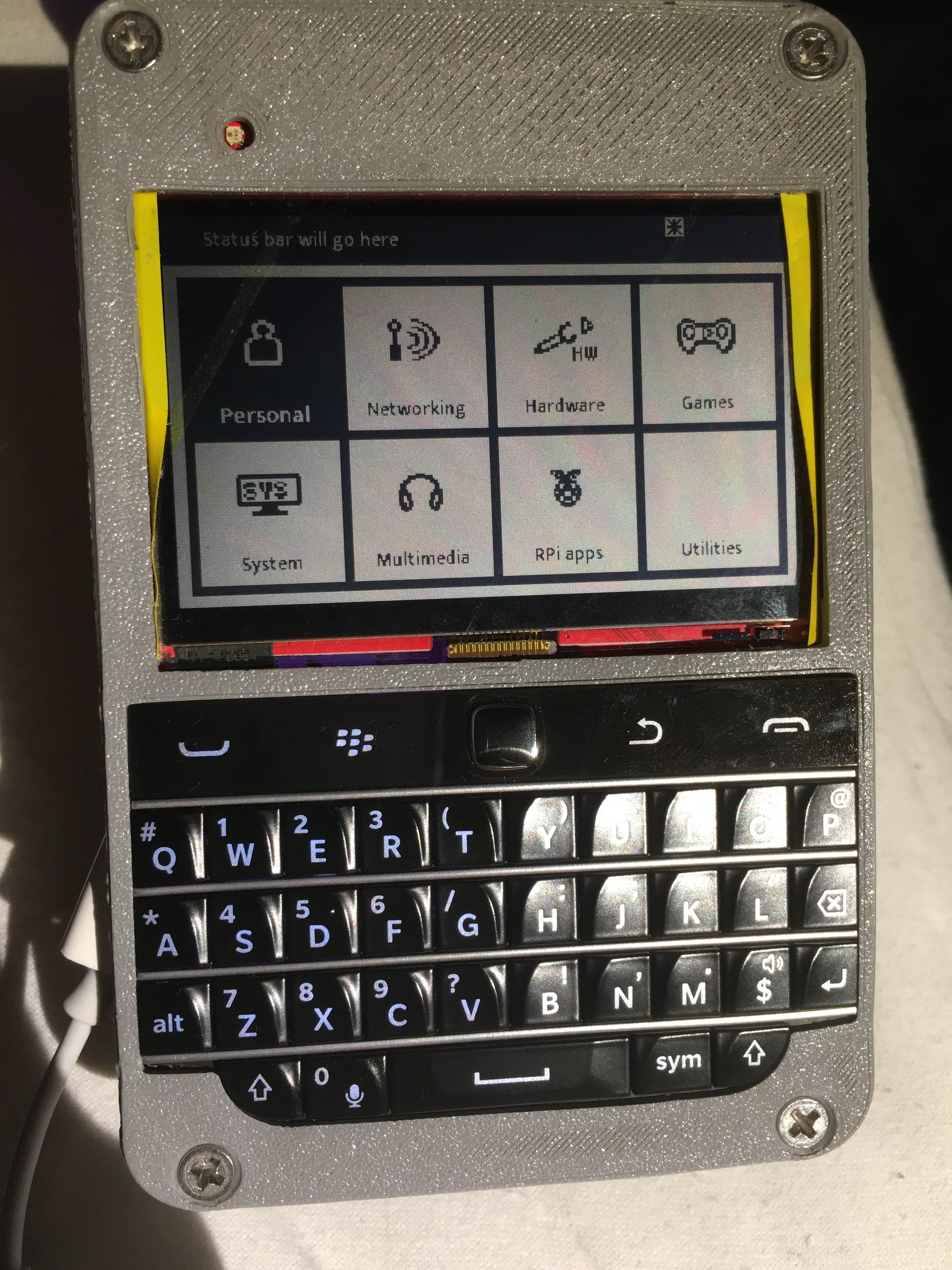
Cheap enough to order a dozen, for $5, only needs an OLED and buttons, and it’s very JLC-compatible
At minimum, you only need a small 128×64 OLED screen and give buttons – for instance, if you have a Waveshare Pi Zero hat, it will do just fine. In case you’re ordering PCBs anytime soon, I’ve also designed a businesscard form-factor Pi shield, which fits on any Pi and even works over QWIIC if you want – throw the board into your next JLC order, solder an OLED and a few jellybean buttons to it, follow the install instructions, and enjoy the extra point of control over your Linux install.
As-is, ZPUI can do most of the basic tasks for you – show network info, connect to WiFi networks (and even display known network passwords), manage system services with help of a systemctl API, poweroff/reboot, unmount partitions so you don’t have to SSH in to unplug that one flash drive, list USB devices so you know if your favourite device fell off the bus, and do a number of other things (there’s even an AVRDUDE app!). It will even let you input console commands through arrow keys in a pinch.
Example ZPUI apps, complete with instructions, coming soon!
Currently, apart from UI improvements, I’m working on a heap of mechanisms to make third-party app designs easier. You already can develop ZPUI apps, and you can even distribute ZPUI apps as Python packages, but there’s still work to do. If you want to help contribute and tackle goals like, say, a raspi-config app or a Bluetooth config interface, you’re most welcome to join in and help – there’s even a ZPUI emulator for app development purposes!
ZPUI is a project aimed to make your other projects easier. I invite you to try it out, especially if you’ve faced the kind of problems I’ve told about in the article intro. If it were up to me, SBCs like Raspberry Pi would come with these kinds of interfaces out of the box, simply because of the insanely large amount of problems I’ve had it solve and figure out.
Unexpectedly Cyberpunk
Here’s a cool demo! I’ve assembled a ZPUI businesscard into a palm-sized shield, with a QWIIC cable connected to it. On my SBCs, I have QWIIC sockets exposed, with ZPUI installed and configured to expect such a shield. When I plug it in, ZPUI detects it on the I2C bus and shows up on the screen. This palm-sized shield feels surprisingly cyberpunk to use, akin to having a cable in your wrist that lets you tap into any device of your choice. For a while now, all my devices come with QWIIC connectors, because of just how much ZPUI helps me in bringup and development.
If you have any questions, ask away, and I hope ZPUI can help you. If not – let me know! This year, I’m aiming to seriously upgrade it, building it into a fully-featured UI it is meant to be, and if there’s a feature you’re looking for, it could very well get implemented alongside.
From Blog – Hackaday via this RSS feed
The original ESP32 may be a little long in the tooth by now, but it remains a potent tool for connected devices. We were drawn to [Max Pflaum]’s ESP32 Dashboard as a great example, it’s an ESP32 hooked up to an e-paper display. The hardware is simple enough, but the software is what makes it interesting.
This is deigned as a configurable notification tool, so to make it bend to the user’s will a series of widgets can be loaded onto it. The device runs MicroPython, making it easy enough to write more than the ones already on place. The screen is divided into four zones, allowing for a range of widgets to be used at once. All the details can be found in a GitHub repository.
We like it for its configurability and ease of programming, and because it delivers well on the promise of a useful device. An ESP32 and e-ink combination with MicroPython apps is something we’ve seen before in the world of badges.
From Blog – Hackaday via this RSS feed
I ran into an old episode of Hogan’s Heroes the other day that stuck me as odd. It didn’t have a laugh track. Ironically, the show was one where two pilots were shown, one with and one without a laugh track. The resulting data ensured future shows would have fake laughter. This wasn’t the pilot, though, so I think it was just an error on the part of the streaming service.
However, it was very odd. Many of the jokes didn’t come off as funny without the laugh track. Many of them came off as cruel. That got me to thinking about how they had to put laughter in these shows to begin with. I had my suspicions, but was I way off!
Well, to be honest, my suspicions were well-founded if you go back far enough. Bing Crosby was tired of running two live broadcasts, one for each coast, so he invested in tape recording, using German recorders Jack Mullin had brought back after World War II. Apparently, one week, Crosby’s guest was a comic named Bob Burns. He told some off-color stories, and the audience was howling. Of course, none of that would make it on the air in those days. But they saved the recording.
A few weeks later, either a bit of the show wasn’t as funny or the audience was in a bad mood. So they spliced in some of the laughs from the Burns performance. You could guess that would happen, and that’s the apparent birth of the laugh track. But that method didn’t last long before someone — Charley Douglass — came up with something better.
Sweetening
The problem with a studio audience is that they might not laugh at the right times. Or at all. Or they might laugh too much, too loudly, or too long. Charley Douglass developed techniques for sweetening an audio track — adding laughter, or desweetening by muting or cutting live laughter. At first, this was laborious, but Douglass had a plan.
He built a prototype machine that was a 28-inch wooden wheel with tape glued to its perimeter. The tape had laughter recordings and a mechanical detent system to control how much it played back.
Douglass decided to leave CBS, but the prototype belonged to them. However, the machine didn’t last very long without his attention. In 1953, he built his own derivative version and populated it with laughter from the Red Skelton Show, where Red did pantomime, and, thus, there was no audio but the laughter and applause.
Do You Really Need It?
There is a lot of debate regarding fake laughter. On the one hand, it does seem to help. On the other hand, shouldn’t people just — you know — laugh when something’s funny?
There was concern, for example, that the Munsters would be scary without a laugh track. Like I mentioned earlier, some of the gags on Hogan’s Heroes are fine with laughter, but seem mean-spirited without.
Consider the Big Bang theory. If you watch a clip (below) with no laugh track, you’ll notice two things. First, it does seem a bit mean (as a commenter said: “…like a bunch of people who really hate each other…” The other thing you’ll notice is that they pause for the laugh track insertion, which, when there is no laughter, comes off as really weird.
Laugh Monopoly
Laugh tracks became very common with most single-camera shows. These were hard to do in front of an audience because they weren’t filmed in sequence. Even so, some directors didn’t approve of “mechanical tricks” and refused to use fake laughter.
Even multiple-camera shows would sometimes want to augment a weak audience reaction or even just replace laughter to make editing less noticeable. Soon, producers realized that they could do away with the audience and just use canned laughter. Douglass was essentially the only game in town, at least in the United States.
The Douglass device was used on all the shows from the 1950s through the 1970s. Andy Griffith? Yep. Betwitched? Sure. The Brady Bunch? Of course. Even the Munster had Douglass or one of his family members creating their laugh tracks.
One reason he stayed a monopoly is that he was extremely secretive about how he did his work. In 1960, he formed Northridge Electronics out of a garage. When called upon, he’d wheel his invention into a studio’s editing room and add laughs for them. No one was allowed to watch.
You can see the original “laff box” in the videos below.
The device was securely locked, but inside, we now know that the machine had 32 tape loops, each with ten laugh tracks. Typewriter-like keys allowed you to select various laughs and control their duration and intensity,
In the background, there was always a titter track of people mildly laughing that could be made more or less prominent. There were also some other sound effects like clapping or people moving in seats.
Building a laugh track involved mixing samples from different tracks and modulating their amplitude. You can imagine it was like playing a musical instrument that emits laughter.
Before you tell us, yes, there seems to be some kind of modern interface board on the top in the second video. No, we don’t know what it is for, but we’re sure it isn’t part of the original machine.
The original laff box wound up appearing on Antiques Roadshow where someone had bought it at a storage locker auction.
End of an Era
Of course, all things end. As technology got better and tastes changed, some companies — notably animation companies — made their own laugh tracks. One of Douglass’ protégés started a company, Sound One, that used better technology to create laughter, including stereo recordings and cassette tapes.
Today, laugh tracks are not everywhere, but you can still find them and, of course, they are prevalent in reruns. The next time you hear one, you’ll know the history behind that giggle.
If you want to build a more modern version of the laff box, [smogdog] has just the video for you, below.
From Blog – Hackaday via this RSS feed