diy

21742 readers
1 users here now

Finally, a comm for that one user who hand-makes longbows. This ones for you, comrade.

founded 4 years ago
MODERATORS
26


Hi friends - still sick, feel like ass, but I did a lot of work recently, and if everything goes according to plan, within 2 more journal entries, I'll be able to report on my very first hair removal test!

What I've been up to

This week was mostly board and circuit design. I just ordered two more circuit boards I designed, here they are:

Current pump, mk2

Schematic:

PCB:

3D PCB:

I talked about this one in Journal Entry #1 - since then, I received the board and the parts for mk1, and it works duck-dance

Technically, this means I can test hair removal on myself, but I'm going to try and wait until I have the new board, for a lot of reasons. Here's what I changed:

  • Before, the current went out a current pump and went in to ground. If the current pump were to malfunction, it would cause more current than expected to leave the probe, which is a safety issue (not electrocution level, but possibly a scarring issue - very bad). I added a current sink hard-wired to 2 mA on the return of the current probe so that even if the current pump fails, the current sink will still cap the max current at 2 mA.
  • I added feedback so that I can measure the output current from a microcontroller. This is pre-work for the Sphynx Uno, and it can also be used as a safety measure - if the current goes too high, I can cut board power and flash an angry red LED as an error light.
  • I added a current knob! This is one more thing to test for the final version.
  • I broke out and very neatly labeled parts of the schematic so that this is an easier resource to learn from as an outsider.
  • I changed up some resistor values to make the current pump and current sink more stable.

My highly scientific outlook on this one is that there's a 75% chance it works as intended first shot.

This is the board I'm going to use to test hair removal on myself (if it works)! If it works, there aren't really any other current pump related changes to make and this one can get incorporated into the Sphynx Lite!

Digital timing, mk1

Schematic:

PCB:

3D PCB:

@macerated_baby_presidents@hexbear.net game me some really good feedback on this one in Journal Entry #2. I since figured out a better way to make the timer work by actually reading the manual for the part I'm using. This means the knob I'm using will actually be accurate and not have a dangerous failure mode! yay!

This one is a little less likely to be perfect on the first try - it is all new, unlike the current source, it's also a little more complicated, and because of that, I'm giving it 40% odds to work on the first try.

When I get these two boards, if they both work as designed, I will be able to plug in a benchtop power supply, rig up some kind of weird holder for an electrolysis needle, and go for a spot of hair on my thigh I've been growing out for this moment! Journal entry 4 will probably be me designing and ordering the battery submodule, so journal entry 5 will be my first report of actual hair removal!

New Developments

We're on git! Specifically sourcehut! https://git.sr.ht/~_410bdf/sphynx

It's somewhat empty right now, it's also especially clunky because I just set it up and all of my commits are just dumping in all of my files, but now people can actually look at my files and mess with them for themselves, or even contribute if there's anything that anyone feels comfy adding!

Next up

As mentioned above, steady progess, waiting for boards to come in, making the battery board, and probably before the end of March I'll be starting to get rid of some body hair. End of April is a very reasonable timeline for a beta version of the Sphynx Lite to be available for enthusiastic individuals to order, build, try, and review! We're getting there!

Any ways to help?

Calls are out for a Sphynx logo for sure! Design review is always appreciated as well! Besides that, I'm just working through the early stuff, things are a little too turbulent at the moment for me to ask for much because things are moving too fast. Once I'm working on the Lite, it'd be SO sick if anyone artistically inclined would want to design some cool silkscreen for the Lite, maybe with a Blahaj, some trans/commie logos, possibly some original artwork - the possibilities are endless party-blob

This one's a little terse because I'm sick and tired, but as usual, from last time - If you have any questions, please ask below! It doesn't matter if they're technical or non-technical, it doesn't matter if you think they're basic, dumb, not worth my time, or anything else - I want people to get excited about this and I would love to take the time to communicate the inner workings of this to y'all so that everyone can be included! I can't guarantee I'll reply to everyone but I'll do my best to reply to comments that are asking something directly or I have something to add to!

27


here is some free and unsolicited advice. agree/disagree?

situations you will want a cordless drill:

  • you are working where there is not guaranteed convenient electricity available
  • you need to be extremely mobile and a cord would be hazardous or very inconvenient
  • wet environments? idk

examples: rough construction, outdoors, drywall racing

benefits of a corded drill:

  • no batteries to charge
  • no batteries that can be stolen
  • no batteries you can lose or break
  • no need to plan around charging batteries
  • no batteries which allow the manufacturer to twist your arm into buying a new device when the old one works just fine; less susceptible to planned obsolescence
  • no batteries to weigh the tool down: lighter and more comfortable to use the tool and better balance
  • tool is smaller and easier to use in cramped situations
  • don't need a case, charger, extra batteries or other junk
  • one less thing to go wrong; more repairable if it does
  • more powerful

you are in a comm called "DIY" = you are probably always working near a power outlet and not going very far. consider a corded drill instead of mindlessly going cordless.

Make sure you get a decent extension cord. I used heatshink tubing to add an extra 6ft to my cord, that makes it long enough for many applications. Sometimes I tie on an extra one.

28


Hello! It has been a week! I did some work on this! Not as much as I'd have liked because I'm sick (I believe not COVID, it's been fairly mild and if it is COVID my vax is fresh but I'm still avoiding doing a lot).

What I've been up to

The main engineering achievement of the week was finishing drafting a schematic for the timing part of the circuit. Brief step back, in terms of development, I am breaking the first version into 3 separate pieces: the power board, the current pump frontend, and the timing board. I'm doing this so I can debug them all separately; if one of them ends up being broken and I need to wait on a new PCB or components, it doesn't block me from working on the other two. Once they all work, I will unite them all into a single PCB that will form the final version of the first release. The timing board is the most complicated of the three, and it itself breaks down further into three more parts (all on the same PCB). These are:

Power conditioning:

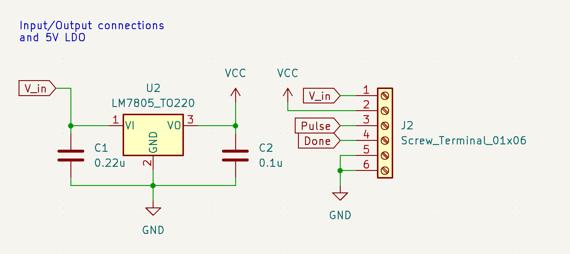
All this is is connectors to hook up inputs and outputs and a basic voltage regulator to turn the input voltage into a clean 5V to do logic circuitry with.
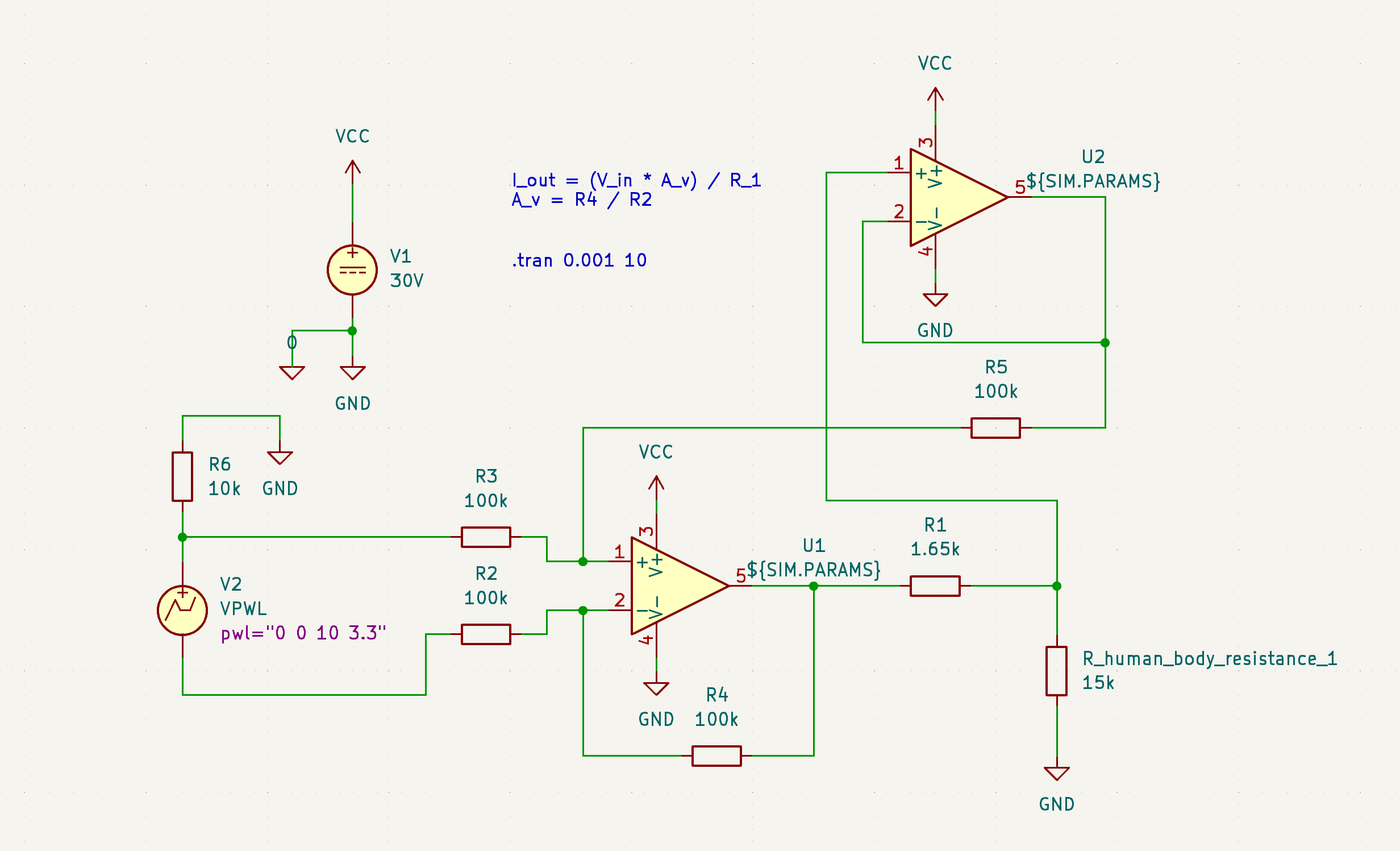
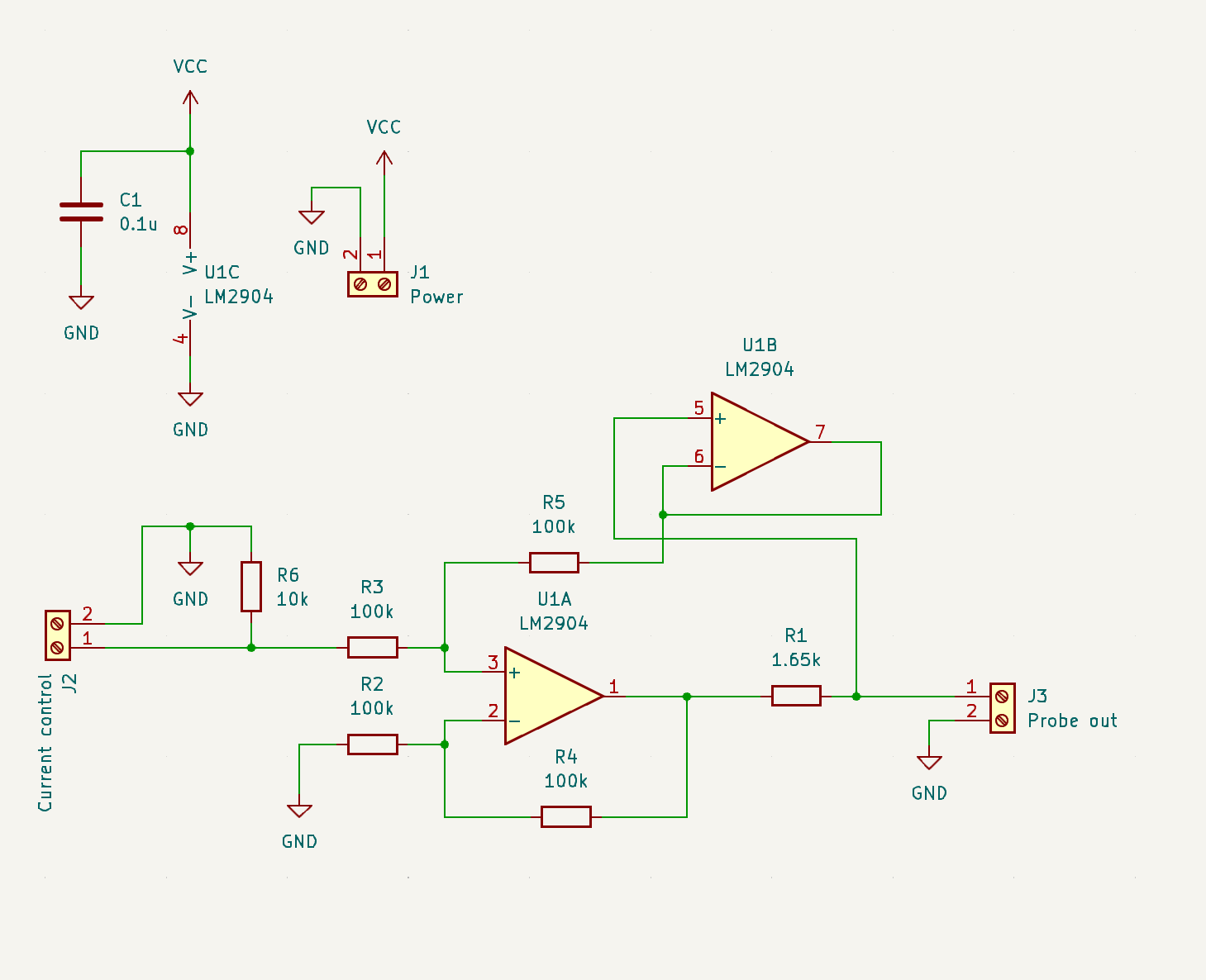
Pulse timing:

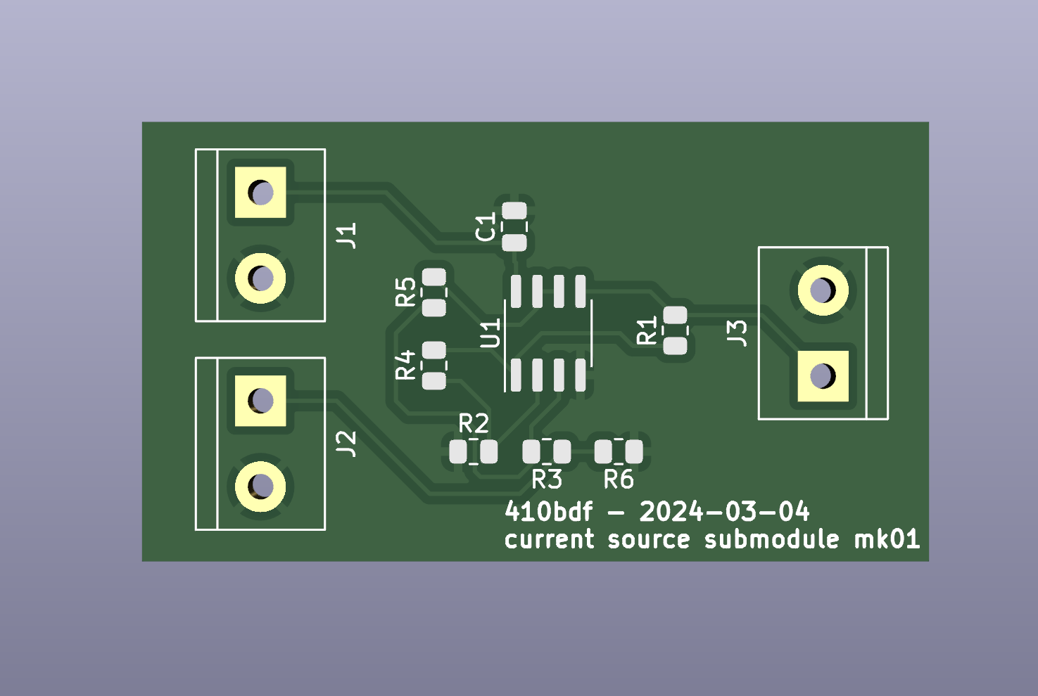
This is the part of the circuit that activates the current pump I drew, layed out, and ordered from my previous post. This thing has a 6.35mm jack that you plug a sustain pedal from a keyboard into (deeply proud of this idea - transfems are literally known for their audio equipment!), and on press, it will start a 5V pulse that is anywhere from 1.5 seconds to 12 seconds long, depending on the position of knob RV1. This 5V pulse will activate the current pump frontend. Notably, I am not using a 555 timer. I spent so. much. fucking. time on this fucking part of the circuit, the 555 was utimately to imprecise to feel good about including it. I was going to use a fucking crystal oscillator to keep good time at one point, and then finally I luckily found out about the LTC6993, which is an awesome 555 replacement that every amateur electronics person should get comfy with because I am never using a 555 ever again. There's still fairly sizeable error from RV1 being +/- 20% tolerance, but at least it's not stacking up from several parts, depending heavily on temperature, or any of the other problems a 555 has. This part would be a thousand times easier with a microcontroller, but at least it doesn't need to be flashed. @macerated_baby_presidents@hexbear.net you tried to warn me and I didn't listen lmao

Feedback

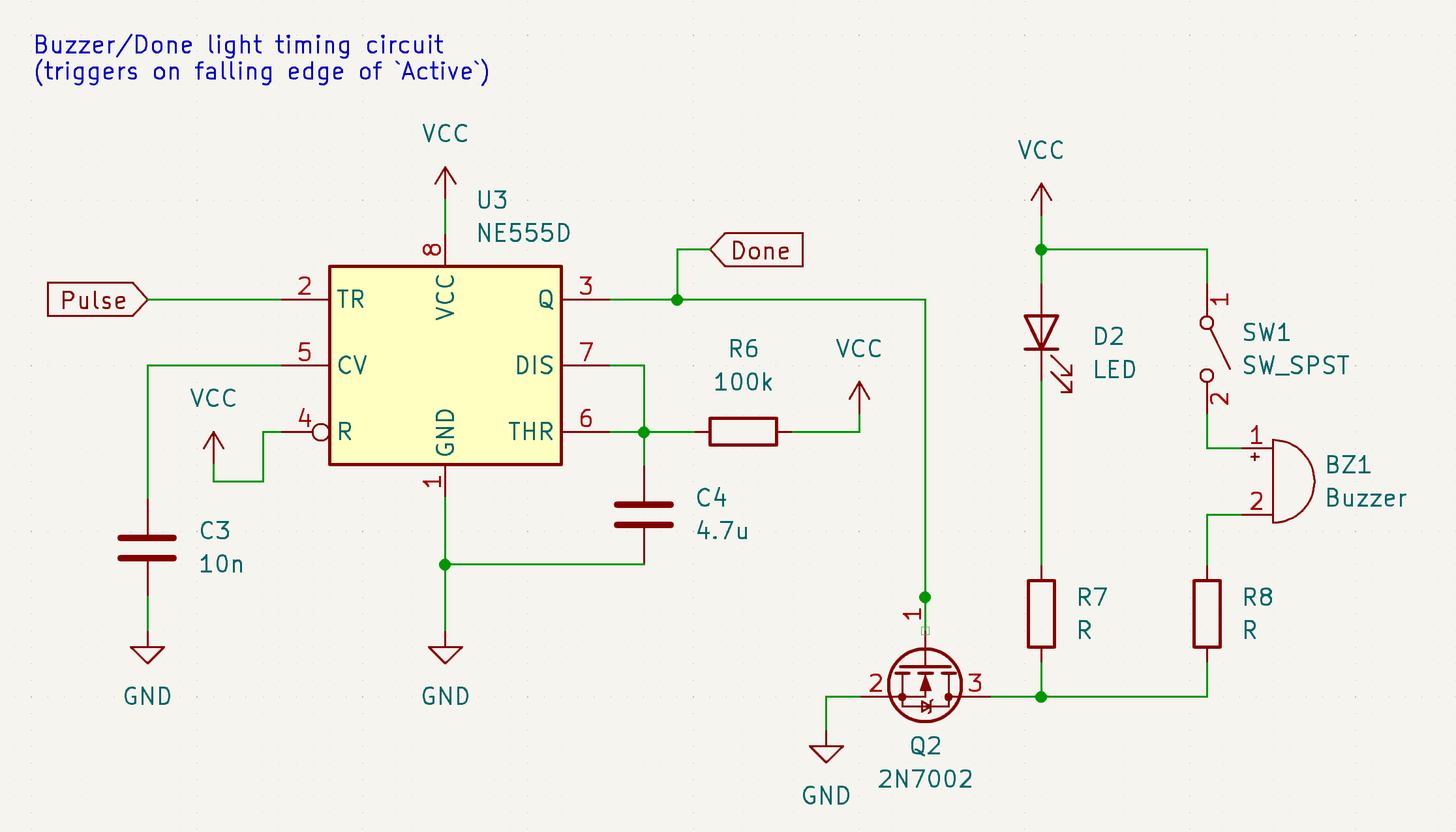
Basically, as soon as the pulse is done, this board will turn on a little "OK!" LED and, if the switch is on, make an audible beep. This one can be a 555 timer because I don't care precisely how long the beep is. Right now it's about a half a second.

These three are all on one board. I still have to identify components to use for some of these (LEDs, buzzer, switch, 6.35mm jack, maybe more?) before I can lay out an actual PCB like I did for the current pump, but that's what I have coming up next.

That's been my week! Not a bad run if I do say so myself.

New Developments

First and foremost, I made some tough choices about how I want to plan things going forwards. I have a long and often times self-conflicting priorities list, so I wanted to come up with a road map that satisfies as many of the goals of the project as possible. So, the road map going forward from my side will be as follows:

  1. First, I'm going to make a push to release the first iteration, the minimum viable product to providing safe, accessible, and effective electrolysis for anyone who wants to make one, with no bells and whistles. This will have a lot of cuts (full list below) but it'll be 100% sufficient to perform electrolysis with and I'll only release it when I've confirmed that it works and it's safe. I'm going to be calling this version the Sphynx Lite.
    1. From here, once the Sphynx Lite is released, things open up for contributors to do more things for the project. This is where I'd love a couple of particularly passionate and initiated folks to get involved and start doing things like writing documentation, designing enclosures, revising the circuit to release a Sphynx Lite 2, and more. Hopefully with the board and a minimal instruction manual I'll provide for its operation and making rudimentary peripherals, we can get an ecosystem going.
    2. Once the Sphynx Lite is out, start work on the Sphynx Uno (Sphynx Ein? just "Sphynx"? Sphynx один? still workshopping this one a lil bit) that will roll in all the nice to haves that I left out of the Lite, while keeping a lot of things I've put effort into and would like to keep, like the current pump.
    1. With the Uno, there'll be firmware - this is where community folks will really be able to shine, for one, this is the thing that the most people expressed interest in helping with, and for two, this is the thing that allows development to be distributed, people to work on multiple things at a time, and the project to really start picking up steam.
    2. Once the Uno is on a clear trajectory across the finish line, that's when we can start working on the final boss, the Sphynx Wave.

Rundown of the 3 models I could ever imagine intending to make:

  • Sphynx Lite: Takes 2 9V batteries. No microcontroller, no screen, likely not even a 7 segment display unless there arises a good safety argument for needing visual feedback on voltage and current, just a knob for max current, a knob for max voltage, and a knob for pulse time, with a beeper and a couple LEDs for feedback, and connectors for a foot pedal activation switch and a probe. All digital and analog electronics - no flashing required.
  • Sphynx Uno: Add a microcontroller, rehash a lot of things that will benefit from having a microcontroller, like timing, input method, and whatever else comes up. Replace the 2 9V batteries with a LiPo with a proper power infrastructure, including boosting, possibly to a slightly higher voltage than the Lite, USB charging, and more.
  • Sphynx Wave: Everything that the Sphynx Uno is, except instead of just the DC current pump on the frontend, add an RF power applicator circuit to the output as well (this is nerd talk for "Uno is galvanic only, Wave is galvanic, blend, or thermolysis").

(thank you to @lilypad@hexbear.net for suggesting the Sphynx name! I think I'm gonna keep it! meow-hug)

I've also decided that open hardware is probably the move licensing wise. It doesn't preclude me ever getting something together to start selling units, but it also keeps this a community project and allows anyone to build it as cheaply as they want to, remix it, or do anything else they'd like to themselves.

Next Up

The components to build and test the current pump are waiting on my bench. I have to build that, test it, and then honestly I can fake the rest with an Arduino and a benchtop power supply to test the output parameters and kill a test area of hairs if there's no bugs in my circuit and start the waiting game to see if they come back. I also have to lay out the timing submodule, and I have to both design and lay out the battery/power submodule. Once they all play nice tied together with wires on the bench, I'll dump all 3 designs in the same file and start weaving them together to make the Lite.

Any ways to help?

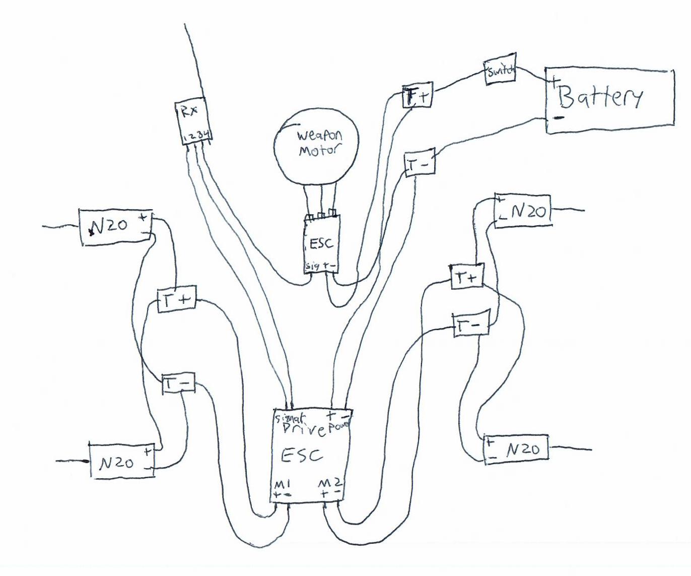
Audit my circuits above for sure, I'm being dumb and ordering a PCB before testing most of this on the bench. I'm going to add some more debugging features to the design before ordering the design, but still it'd be nice to catch as many mistakes as possible early. I also have an interesting request:

https://synopticproducts.com/collections/f-shank/products/ballet-f-and-k-shank-needle-holders?variant=40311122100305

Synoptic seems to be using a modified mechanical pencil as a probe - does anyone recognize this make of mechanical pencil? I'd love to get some and see if they lend themselves well to being made into probes. I owe you all an actual drawing of what the probe should look like and do next time too, it'd be awesome if someone could figure out how to make the probe work. If anyone feels like taking a stab at it now though, ask anything you'd like to know, but in short, all it needs to do is hold onto an F-shank needle with electrical continuity in a way that is easily replaceable and can be held like a pen. Bonus points if there's some type of shroud to cover the tip when not in use, but that's not a huge deal, it's more important that this doesn't require any advanced tools - accessibility.

Now that I've committed to a name, we can start thinking of a logo too! The added bonus of using a cat is that it's extremely reasonable to incorporate a ":3" into the logo. I would love to see suggestions if anyone's bored and looking to help! My only ask is that it should have a good monocolor representation and that it doesn't have any tiny features so I can put it on the PCB itself. If you can draw it with a sharpie, it'll work perfect.

If you have any questions, please ask below! It doesn't matter if they're technical or non-technical, it doesn't matter if you think they're basic, dumb, not worth my time, or anything else - I want people to get excited about this and I would love to take the time to communicate the inner workings of this to y'all so that everyone can be included! I can't guarantee I'll reply to everyone but I'll do my best to reply to comments that are asking something directly or I have something to add to!

Tag list is in my top level comment below, reply to that comment if you want to be added or removed. Love you. Thanks for being here. I hope I can do good by my favorite internet people. :trans-heart:

29


Hi! As promised, here's my progress so far. This post will also be the loose format of how I want to post these in the future. I intend to have four sections: what I've been up to, what new developments have come up, and what I have planned next, and if there's any immediate opportunities to help. I also want these to be written casually so I don't have to agonize over them, and so that they're fully readable by technically experienced folks but also skimmable with occasional tl;drs for curious but not electronics literate onlookers.

What I've been up to

In ultra brief summary, my last week on this project was giving up on the LM334, which is a lovely chip if you want a precision low-amperage source (seriously I was getting stable single microamp precision), but it just has too many quirks for use as an on the fly adjustable current source. I've since committed to a dual opamp design I found on some blog somewhere and I haven't looked back, because it seems to work perfectly. I designed a circuit, simulated it, it worked swimmingly, I laid it out on a PCB, ordered it, and ordered parts to build it out.

Here's the blog post - I went with the "Two Op-Amp Topology". It's actually sick as hell. Here's my implementation of it in SPICE:

Something I'm really adamant about on in regards to safety (a core objective) is that this needs to have hard limits on both current and voltage. I've been able to design this in in the simulation, see:

It's hard to tell exactly what's going on here if you don't know how to read circuit diagrams and also know how I set this up, but essentially, I'm varying the simulated human body resistance and looking for it to behave the same way as I do so. Even if the device can drive the amps into you by current and voltage availability alone, it's hard capped at 2 mA, with the voltage limit imposed by whatever voltage you give the opamp and the current limit imposed by (basically) the resistance of R1. (More technically, this is a voltage controlled current source, and the voltage applied to V_current_set is divided by the resistance of R1 for the value of the current sourced from U1A.) All bodies are not the same resistivity, all parts of the same body are not the same resistivity, and even the same part of the same body is not always going to be the same resistivity. It's important that the administered current and voltage don't vary based on user, body part, and et cetera. This is an important safety and performance feature that most other DIYers I've seen have omitted. This is exactly what I was hoping to see this design do and it nailed it.

So, I drew up the circuit, routed the PCB, and with that, we're here:

It comes in the mail next week! Thanks to @lapis and @macerated_baby_presidents for the JLCPCB rec, I didn't get a populated board, I wanna build it myself, but their service has been nice so far and I look forward to ordering a populated board from them soon to test accessibility! I left off test points, status LEDs, and some other stuff. That's okay. I'll do better next time. :comfy: The important thing is that this circuit is the circuit I'm rolling into 1.0.

Non-technical tl;dr: This is the circuit that takes in a normal power source and conditions it into the correct amount of power, specifically voltage and current, to kill hair follicles in a safe and controllable fashion.

New developments

I decided to give up on microcontrollers. 💔 For now.

Adding a microcontroller adds a lot of pros, and a lot of cons. The upshots are that it really makes this into something cool, something with flipper zero vibes - I'd be able to add a splash screen with graphics and I'd be able to explicitly list voltage/current/pulse time numbers on a display, I'd be able to shift a number of changes into firmware over hardware, meaning quicker debugging, and more. The downside though, is that I'd likely be requiring end users to flash a firmware build (not accessible, breaking one of the core 3 objectives), I'd be dealing with a data bus like SPI to get the screen to run, which is a pain to debug, and I'd be opening myself up to feature creep. I decided to axe it for now and just do everything by knobs with no screen to be able to get y'all a working basic finished project sooner. ❤️‍🩹

Next up

My availability is somewhat limited for the next week, but I want to at least build out this board and test it on the bench to make sure it actually applies the current I designed it to. While I'm waiting for this, I can start to design the other parts of this circuit. I have the power conditioning designed, next up I need to design the following, roughly in this order:

  1. instead of just loose inputs I put voltages on, I want to make knobs that set the amperage.
  2. I need to add timing circuitry so that instead of just an on/off, the user pushes a button and the device outputs current for an amount of time configured by a second knob.
  3. I need to add power conditioning, so that a 9V battery, an 18650, or something like it can be boosted up to generate the voltage required to drive the current required to smoke ur hairs.
  4. Fit and finish. Oh, and all of the activation switch and applicator probe everything.

I can probably design 1 and 2 in the next week. I definitely won't be able to actually build and test them until late next week, but now that I'm getting better at SPICE, I can simulate them, which will give me the (probably ill-founded) confidence to order boards without testing anything on the bench first. Likely no updates until mid next week due to this.

Any ways to help?

First of all, ask to be put on the tag list if you want updates! Knowing there are other real life human beings who think this is cool helps me a lot. Besides that, no electronics help at the moment, I don't have enough done to have any shared work to propose. Soon, I'll start thinking about the current probe, and I'll need help thinking about that. Besides that though, just get hype and if you know anyone who knows anything about electrolysis hair removal, let them know about this so they can be here for discussions if they want to be!

I'll see y'all some time next week for the next update. Thursday of next week or earlier. It's in my calendar. Bye!


tag list: @ComradeEd@lemmygrad.ml, @raven@hexbear.net, @Wake@hexbear.net, @BountifulEggnog@hexbear.net, let me know below if you want to be added or removed!

30
 
 
31


Made of 10 awg copper wire and 18 awg silver plated wire. Copper work hardened more than I thought, wish I went with 12g instead, but it does make the final result sturdier.

32


The engineers asked me to bisect a part so they could inspect a couple welds. I NAILED it. A few hours later, they came back and asked if I could remove another slice at an angle because they thought the EDM wire might have been getting stuck in the cracks (this is not how EDM works, the wire NEVER touches the part, because if it does that means you get no sparks, and no cut... but regardless).

So here I am, the first cut was already diagonal so I could get both welds in one slice, now I'm fixturing this shit up on a sine plate, indicating the part to get it lined up again, trying to rotate a diagonal plane in 3D space and only give it a couple thousandths of an inch shave.

33


exactly what it says on the tin

34
1
Yeah (hexbear.net)
submitted 2 years ago by RNAi@hexbear.net to c/diy@hexbear.net
 
 
35
36
1
submitted 2 years ago* (last edited 2 years ago) by Mehrunes_Laser@hexbear.net to c/diy@hexbear.net


:sicko-laser:

37


*Pictured: the original GIANT ENEMY CRAB and work in progress JACKALOPE *

I will be linking parts I use as examples. They are not necessarily recommendations for parts or suppliers, I just want you to see what I'm talking about.

Hey sickos, spring_rabbit here, that weirdo who keeps posting about BattleBots. I thought this com could use some more long content, so I'm going to do a build blog of my next combat robot project here. In this post I will be introducing the GIANT ENEMY CRAB 2 project and talking a lil bit about the electronic components I will be using, and I will document future work on the robot as well to keep track of its progress.

PART 1: INTRODUCTION

In the winter of 2021 I finished building my first fully-functional combat robot, GIANT ENEMY CRAB. GEC is a 4 wheel drive robot with a horizontal spinning hammer up front, driven by a drone motor inside the chassis. It weighs just under 1 pound and uses simple 3d printed materials to comply with my local league's "Plastic Antweight" division. The chassis and weapon are made of PETG (one of the few materials allowed in the Plastic Antweight class), the tires are cheap foam wheels I found online, and it uses a hair tie for a weapon pulley belt. It's bulky, ugly, the wiring job sucks, and while the hammer could easily break your finger once spun up, it doesn't do a ton against similar opponents. But it was my first robot and that is something special.

Since last winter though, I've learned a lot. My other antweight JACKALOPE is coming along nicely and a quick glance shows how much more compact and efficient I can get with my designs. So with much more experience under my belt, I'm looking to build a new version of GIANT ENEMY CRAB, using better materials and more knowledgable design to make a much more competitive bot. Unlike the original, GEC2 will be made for the standard 1lb Antweight division, allowing much more flexibility in materials I can use, including engineering filaments and laser-cut metal parts. This is at the request of its future driver, who wants to compete alongside me in the more destructive 1lb weight class.

So what will make GEC2 a proper successor to the original GEC?

  • It will retain the wide 4wd horizontal spinner design.
  • Same electronics (mostly), with better hardware, design, and materials.
  • Angery eyes - so angery
  • Crab

PART 2: ELECTRONICS

The electronics used in GEC2 will be the same as in the original GIANT ENEMY CRAB, save for some upgrades to the battery and power switch. This is because I bought multiples of each of the original components and don't want them to go to waste.

Like most small combat robots, GEC2's electric components will consist of a Battery, Brushed motors for drive, a Brushed Electronic Speed Controller (ESC) to control the drive motors, a Brushless motor for the weapon, a Brushless ESC for the weapon motor, a Receiver, and some switches and terminal blocks. Each of these parts are pretty typical for the weight class, but I will break each of them down here.

Battery - The original GEC used a 2S 300mah battery. It works, but that size of battery is more commonly used for 150g fairyweight/British antweight bots. I will be bumping it up to a 3S 450mah battery which is much more common for this weight class.

Drive Motors - Much like the original, GEC2 will be using 4 1000rpm N20 micro gearmotors to drive it. These are a little small for the weight class, but using 4 of them is enough to carry 1lb just fine.

Drive ESC - The big choice with drive ESCs is whether you want to have a separate ESC for each motor, or one that drives both of them. Dual ESCs are really convenient and cheap, but also bigger and thus a little harder to fit into your design. This is the one I use. In my experience it will run the 4 small motors just fine if I assign two motors per drive channel, and it has a similar footprint to the battery which makes designing an enclosure easier.

Weapon Motor - The weapon will be driven by a MT2204 drone motor. I don't actually like the mounting system on these and prefer a thinner shaft and top that you can screw into, but they come in sets of 4 and I've only used 2 so far. Next time I'm buying parts, it's something I will look out for.

Weapon ESC - The weapon motor will be driven by a 20A Brushless ESC. Again, these came in sets of 4 when I bought them, but unlike the motors I have no complaints. These make the motor go spinny!

Receiver - I like this receiver. I'ma be real, I don't know anything about receivers, but this one is compatible with my transmitter (controller) and has enough channels to run this bot so I see no need to change things up.

Switch/Terminal Blocks - In the original GEC I used a tiny spdt switch to power it on and off, and all of the wire connections are horrible tangles of badly-spliced wire. This time, I will be using a Fingertech switch, and terminal blocks for all 3-way connections. These are mostly for convenience sake as I don't think there is any reason I couldn't do things the old way. I just like these way more for ease of construction and repairability.

So nothing too special as far as electronics go. These are mostly just what I had on hand, and very typical of 1lb bots. Mostly the same as in the original GIANT ENEMY CRAB but with better battery, or like JACKALOPE with different drive motors. The real magic of bot building happens when you start to put a shell around it all...

NEXT: Let's open up Fusion 360 and build a first draft chassis!

update: the wiring diagram update 2: Preview for what I'm doing next

38


It's Robot Fighting Time!

Remote Control Robot Combat is a sport where competitors build remote control vehicles, generally with armor and weapons, which then fight against each other in a walled-off arena. It’s a competition based on good design, good construction, and good driving, with all three necessary to succeed in any given competition.

Remote control robot combat traces its lineage back to 1987's Critter Crunch, organized by the Denver Mad Scientists Society at Denver's MileHiCon, conducted on a hotel table which competitors were forbidden from damaging. This ad-hoc competition began a sport that quickly took off across the world, particularly in the Anglosphere (but not exclusively! Brazil, Russia, and China also have vibrant scenes, and India and Pakistan have begun making their way into international competitions). The sport got a big publicity boost in the 90s with the airing of Robot Wars in the UK, and later BattleBots in America, which became the two premiere televised leagues each with their own peculiarities and rule differences.

While Robot Wars has been cancelled, uncanceled, and cancelled again, BattleBots still airs a yearly competition on Discovery Channel, where teams build 250lb machines with hammers, spinning blades, flamethrowers, and other weapons to fight for the coveted Giant Nut. Gone are the hotel tables and ad-hoc rules - over the last 35 years the rules, technology, and metagame has evolved into a stiff competition where teams will put thousands of dollars and man-hours to make sparks fly in the BattleBox.

Don't have thousands of dollars or big business sponsorships that will pay for your bot? While the 250lb heavyweights suck up most of the attention, robot combat happens at many weight classes, with hobbyists also competing at the 150 gram, 1 pound, and 3 pound leagues, with the biggest "insectweight" league being Connecticut's Norwalk Havoc, where 3lb beetleweight robots fight over the course of a weekend, streamed on YouTube for all to see. There are also 12lb and 30lb leagues, but I don’t know enough about them to speak confidently.

New competitors will often start with a robot kit, such as a Fingertech Viper for the 1lb “antweight” class or a BotKits D2 for the 3lb “beetleweight” class. These come with essentially everything needed to compete minus the transmitter (controller), and you can expect to see several of them during any large open event. Of course, if you have a 3d printer and know what parts you need, it can be much cheaper to roll your own. I estimate that an average 1lb bot costs me between $100 and $200 in parts and spares, but that number can increase rapidly with different weight classes or if I get too creative with exotic materials (I love titanium!).

I could talk about robot combat all day, but instead, here are a couple classic fights from each of the major franchises, showing many of the different weapon types you might see in these competitions.

🪚 Carbide vs Eruption 🌋 (Robot Wars 2017)

🔨 Shatter vs End Game 🥝 (Battlebots 2020)

🐸 Polywog vs Silent Spring 🍃 (NHRL 2022 3lb, both drivers also pilot BattleBots heavyweights Ribbot and Sawblaze, respectively)

Announcements & Information

Megathreads and spaces to hang out:

Reminders:

  • 💚 You nerds can join specific comms to see posts about all sorts of topics
  • 💙 Hexbear’s algorithm prioritizes struggle sessions over upbears
  • 💜 Sorting by new you nerd
  • 🌈 If you ever want to make your own megathread, you can go here nerd

‏‏‎ Links To Resources (Aid and Theory):

Aid:

Theory: