Ask Electronics

3772 readers
1 users here now

For questions about component-level electronic circuits, tools and equipment.

Rules

1: Be nice.

2: Be on-topic (eg: Electronic, not electrical).

3: No commercial stuff, buying, selling or valuations.

4: Be safe.


founded 2 years ago
MODERATORS
176


Hey all, have I damaged this xbox 360 controller circuit board beyond repair?

The Pictures

https://imgur.com/a/oum8Yg4

  • The Red circle is the side I managed to fix.
  • The Blue circle is the parts I could not get to bind properly.

The issues and my process

So I had a pair of xbox 360 controller controllers with corroded battery terminal springs. I managed to successfully replace the first controller's springs, but the second I was having trouble with. The solder would not bind to the pad and it would form a lump that would break off under any pressure.

I consulted the internet and someone mentioned I just needed to crank up the heat. That didn't work and the binding seemed to get worse, further it looks like it is now burnt all the terminal pad.

The internet then told me to scrap away the surface as it might be residual flux and it should be fine underneath. It still fails to securely bind.

I suspect the corrosion ate so far into the device that the pad itself was too weak to bind. I also suspect I am an idiot.

Is there any saving this?

My Plan should I discover I borked it

360 controllers have additional terminals on the back which I might be able to connect to something instead of the battery pads.

177


Hey everyone,

I'm a complete beginner in the world of soldering, and I'm facing some frustrating issues with my soldering iron tips. After just a few minutes of use, my soldering iron tips can't melt the solder anymore.

I always keep a sponge nearby and make sure to clean the tip frequently, just like I saw in tutorials. However, the tips still look a little "burned"/ black. Am I doing something wrong? Or could it be related to the soldering equipment I'm using? I bought a $20 kit on Amazon just to practice.

178


I'm trying to use an LIS2MDL ic with an Arduino nano on a custom PCB designed in KiCad. I tried the Arduino example compass script for the ic and it didn't work. It just prints "Magnetometer Test" and nothing else happens

179
11
submitted 2 years ago* (last edited 2 years ago) by RAM@discuss.tchncs.de to c/askelectronics@discuss.tchncs.de


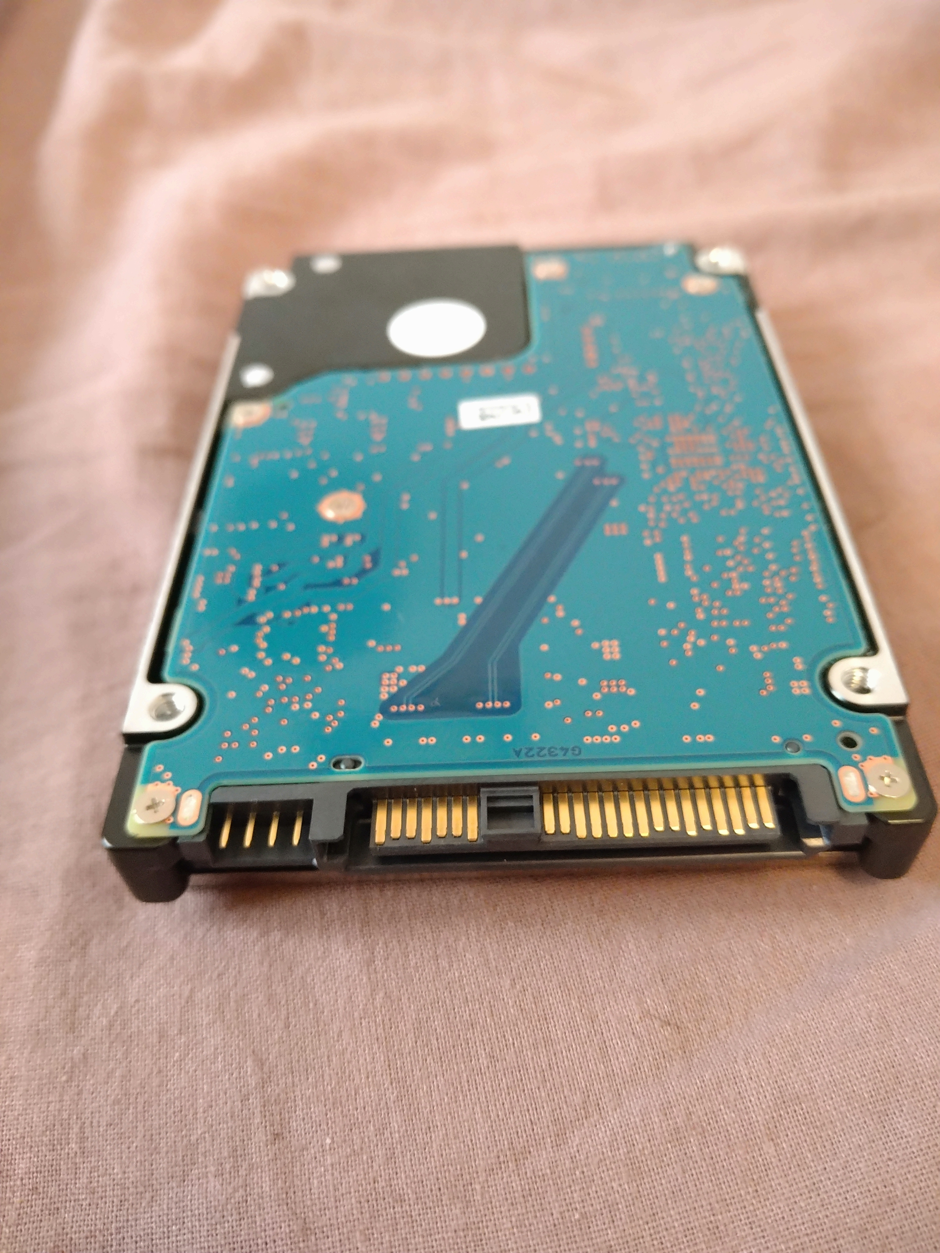
//Edit: It's a SAS drive. thanks for the help :))

I bought two of these a long time ago, and I recently tried to connect them to a SATA III connector without luck. The size seems to match up, but the block between the two pin segments seems to block it from connecting with SATA III.

Can you help me figure out what kind of adaptor I need ? :))

180


Hello, I have a circuit that will need to return connected hardware to a default state if power is lost. The hardware can handle continuous voltage, so I'm thinking a simple solution would be to use a battery to provide that fallback power source. To avoid draining the battery, I'd like to connect it through a relay on the normally open contact and energize the relay directly from the main power supply on my board.

Do I need to look for anything in particular to make sure the coil on the relay I choose can sustain constant voltage for potentially months at a time without damage? Or, is there another similarly low cost and simple solution you'd recommend?

The circuit runs on 12VDC from a [Mean Well IRM-10-12 (specification), and the relays I have on hand are OMRON G5LE-14-CF 12VDC (specification). I don't see anything on the relay documentation that specifies a maximum duty cycle.

181


I'm curious and am playing around with a new EDA tool and am looking at practicing by designing a PCB which should be roughly 28x26mm footprint (give or take a few mm...).

It should be an LTE cat 4 device, connected by USB type C for the framework laptop and is unlikely to include antennas.

Where I struggle is identifying potential modems to use. The only one even remotely close is the u-blox LARA-L6, which is 24x26mm. What alternatives are there?

I am trying to see what gets sold in these USB dongles but there is little info. The few I have identified seem to make use of the Qualcomm 9207, but its's unclear to me if its a ready chip (which is what the MDM9207 is?) Or if it is an IP core to integrate in one's own chip?

A video I came across seem to indicate it (the MDM version) is tiny:

https://www.youtube.com/watch?v=ToCyUCIoXEM at 2:13

But will probably needadditional things to be integrated and I created an account at Qualcomm but they won't give anything unless I'm certified from a company to be a customer and actually integrate it...

182


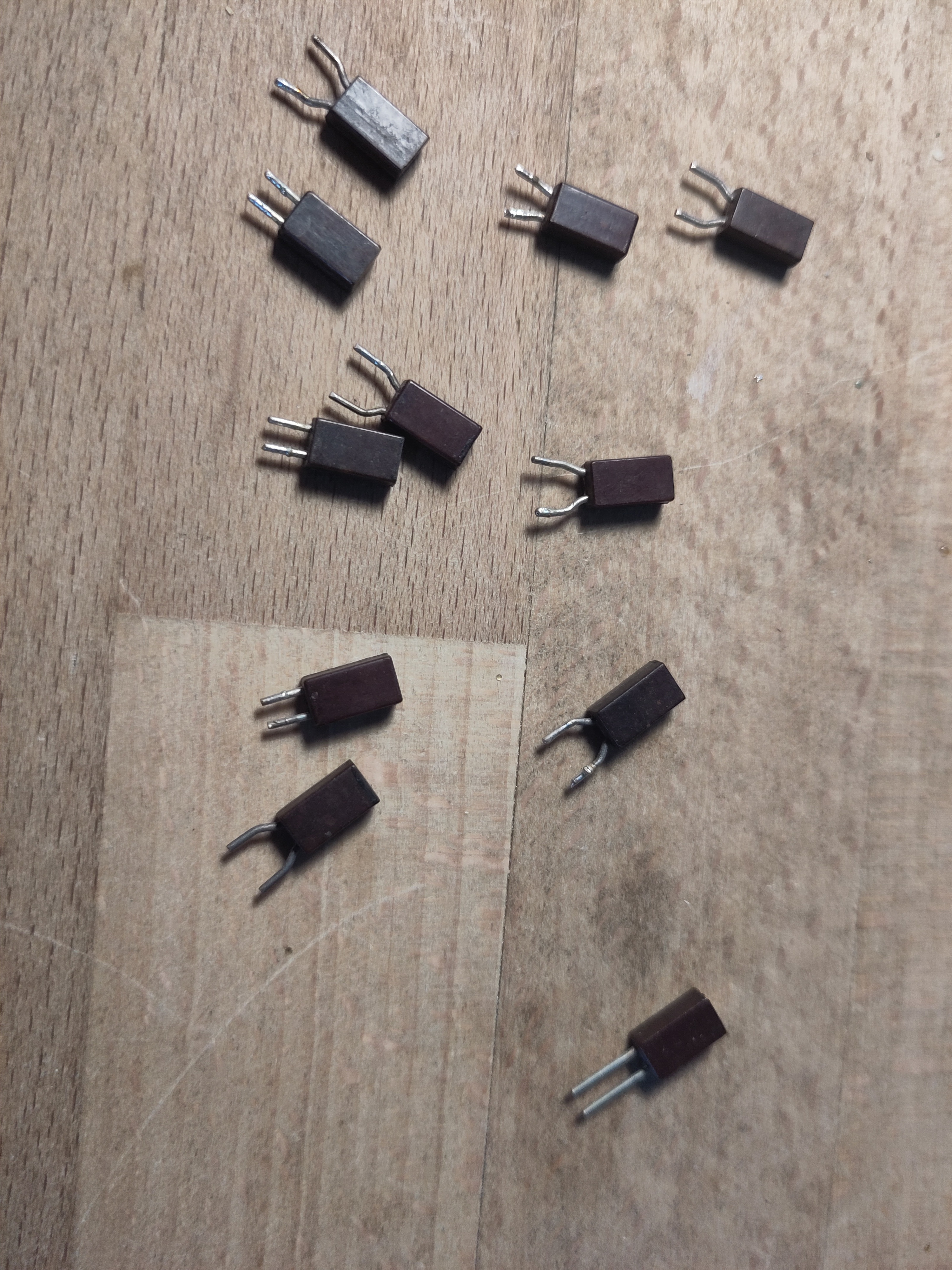
I have a whole bunch of them. They are possibly a bit older (70s, 80s) judging by other contents of the junk box they are from.

There are no labels of any kind, but on the top they have stripes that look hand painted.

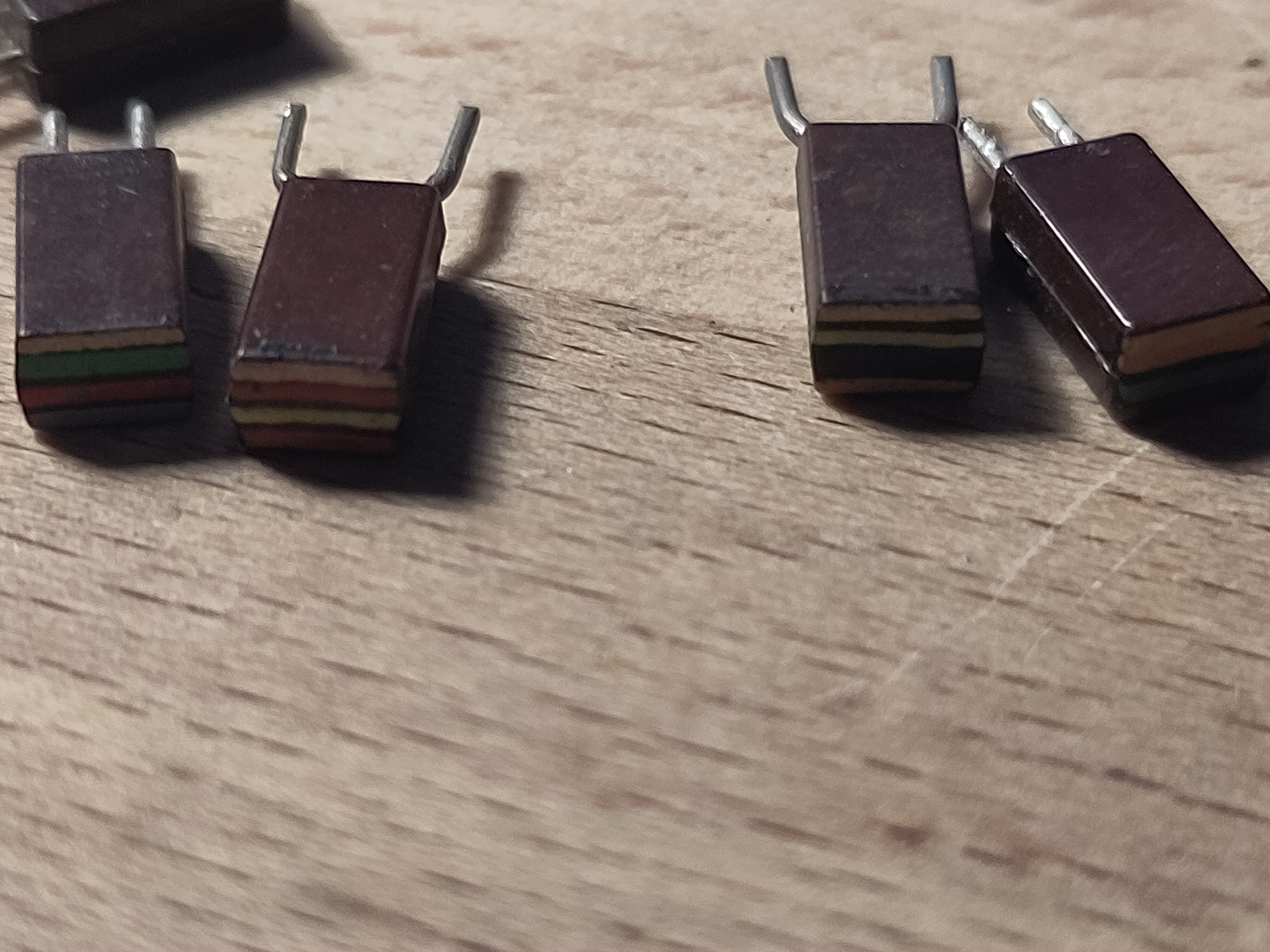
For at least some of them the resistance roughly corresponds to the color code.

So, I'm just curious why I can't find anything about these on the internet.

183


As the title says, I'm looking for a Linux/macOS-compatible EPROM programmer. I'd like to be able to program parallel (E)EPROMs in the 27xxx range. The newer XGecu programmers seem to not be compatible with Linux/macOS, and the selection of TL866(II) clones is too overwhelming for me to be able to choose one.

Any suggestions?

184


This photo shows the power conversion side of two versions of the same board. Input is up to 60V DC, board converts to 5V and then down to 3.3V.

The top board works correctly all the time. But the bottom board has strange issues. Everything works perfectly when I connect it to my bench power supply at 53V. The board powers up with no problems. When I connect it to the daisy chain of other boards, it suddenly will no longer power on, despite ~54V being passed through correctly to downstream boards.

This is a real head-scratcher for me, and I'm having trouble making sense of it. I'm not so much looking for The Solution as to what steps I should take to troubleshoot this. There were some issues attaching the image, so in case it doesn't show up.

https://photos.app.goo.gl/MCx7Q4BDbKTv68EJ8

185
7
submitted 2 years ago* (last edited 2 years ago) by Machinist@lemmy.world to c/askelectronics@discuss.tchncs.de


Circuit is for controlling the fan on a Raspberry Pi, just on/off according to temp, no PWM. Not sure about the diode as it has a .7V drop and it's a tiny brushless DC motor. No markings on the fan so I measured the current with a multimeter when hooking it up to a USB charger. Circuit was adapted from here using what I have on hand.

Suggestions? Any advice is greatly appreciated!

*EDIT: Confirmed, this circuit works on a Raspberry Pi 4. Base was wired to GPIO 17 and manually tested using commands:

raspi-gpio set 17 op dh

raspi-gpio set 17 op dl

I didn't use a breadboard, just hack-n-slash with the wires coming out of the fan, the leads on the thru hole components, a jumper connected to gpio 17 as a socket for the base/resistor lead, and heat shrink tubing for insulation. Folded it up as I closed the housing. Case combo including heatsinks and fan here.

186


Pretty basic question but I am struggling to find the words to get the correct search result. The soldering iron I bought came with very narrow tips that I think are supposed to be used for circuit boards and components.

When I attempt to solder lines from a USB cord together the line never gets warm enough.

I remember in the past soldering copper lines together from an appliance with no issue so I don't think I'm doing anything wrong in terms of technique but who knows?

187


Do any of you have experienced good products for tinkering together with a 3 year old?

I thought about something like a giant breadboard with simple connectors to switch on a light or play a sound or something.

It doesn't have to be too fancy, just sturdy and safe to play together with an adult.

Thanks!

188
27
submitted 2 years ago* (last edited 2 years ago) by ekZepp@lemmy.world to c/askelectronics@discuss.tchncs.de


189


This is my electromagnet.

190


Hello there, This oscillator is a 0V +10v DC oscillator, which after current passes through the capacitor, it produces a -5v +5v AC on the resistor.

We've all heard that AC removes DC component and let's AC pass by. I understand the dynamics of this circuit in case the oscillator were operating with AC (capacitive reactance), however this oscillator is DC, the voltage across the capacitor never changes polarity (since the other side of circuit is ground), so what gives? And why the 10V DC is split on half +5 -5 volts after the capacitor? Thank you!

191


Hi! I'm working on an arduino project that has a -12v/0v/+12 psu. +12 is fed directly into arduinos voltage regulator, so there's also a +5v line available. I need to convert a -5v+5v signal to 0v+5v to feed it into arduinos analogue input and I've already mocked up a schematic in circuitjs based on an opamp that seems to do what I want. The only problem is that it needs -5v to shift the signal to be unipolar. I know that I can invert +5v using another opamp, but maybe there's some simpler way? I'd really like to avoid adding another opamp just for this? In this schematic I used simple voltage divider to get the needed voltage, but I guess that's not the best approach?

TLDR: I have -12v, 0v, +12v and +5v, what's the easiest way to get -5v?

192


Hi!

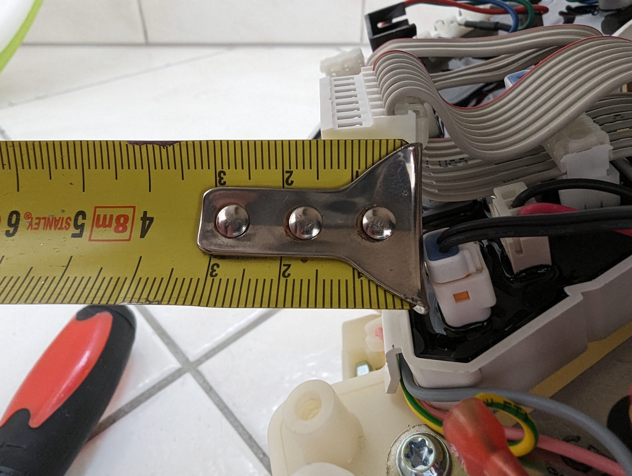
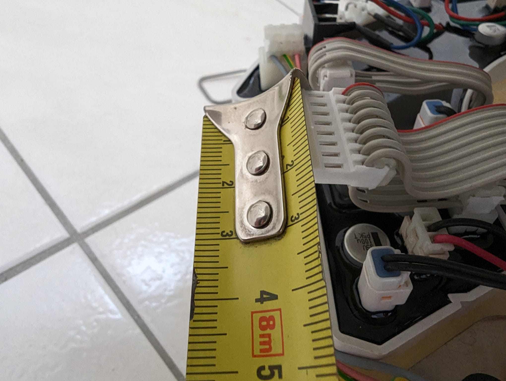
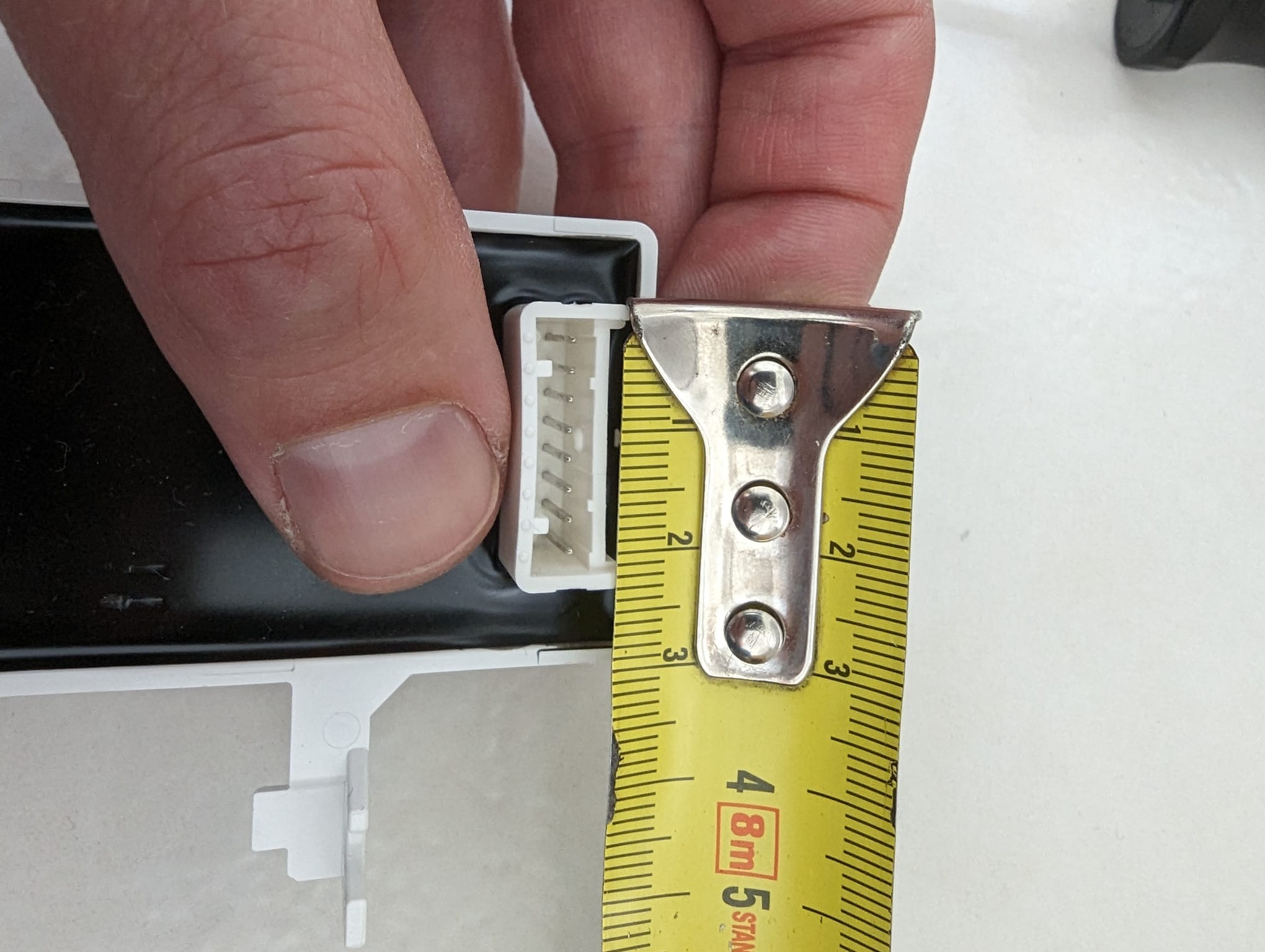
I have bought a Geberit shower toilet/bidet with a motion sensor but it's aimed at the front while the toilet is installed sideways. So I've opened the thing up and I can take out the motion sensor, but the cable it's connected to is too short to do anything with. So I'm looking to buy/make an extension cable, but I have no idea on how to find it. So I took pics of the connector and I'm hoping you can help me find the type of connector (and if someone has a buy link: even better!). Thanks!

edit: https://www.jst.com/products/insulation-displacement-connectors-wire-to-board-type/vr-connector/ this looks like the socket, but the pitch seems wrong?

193


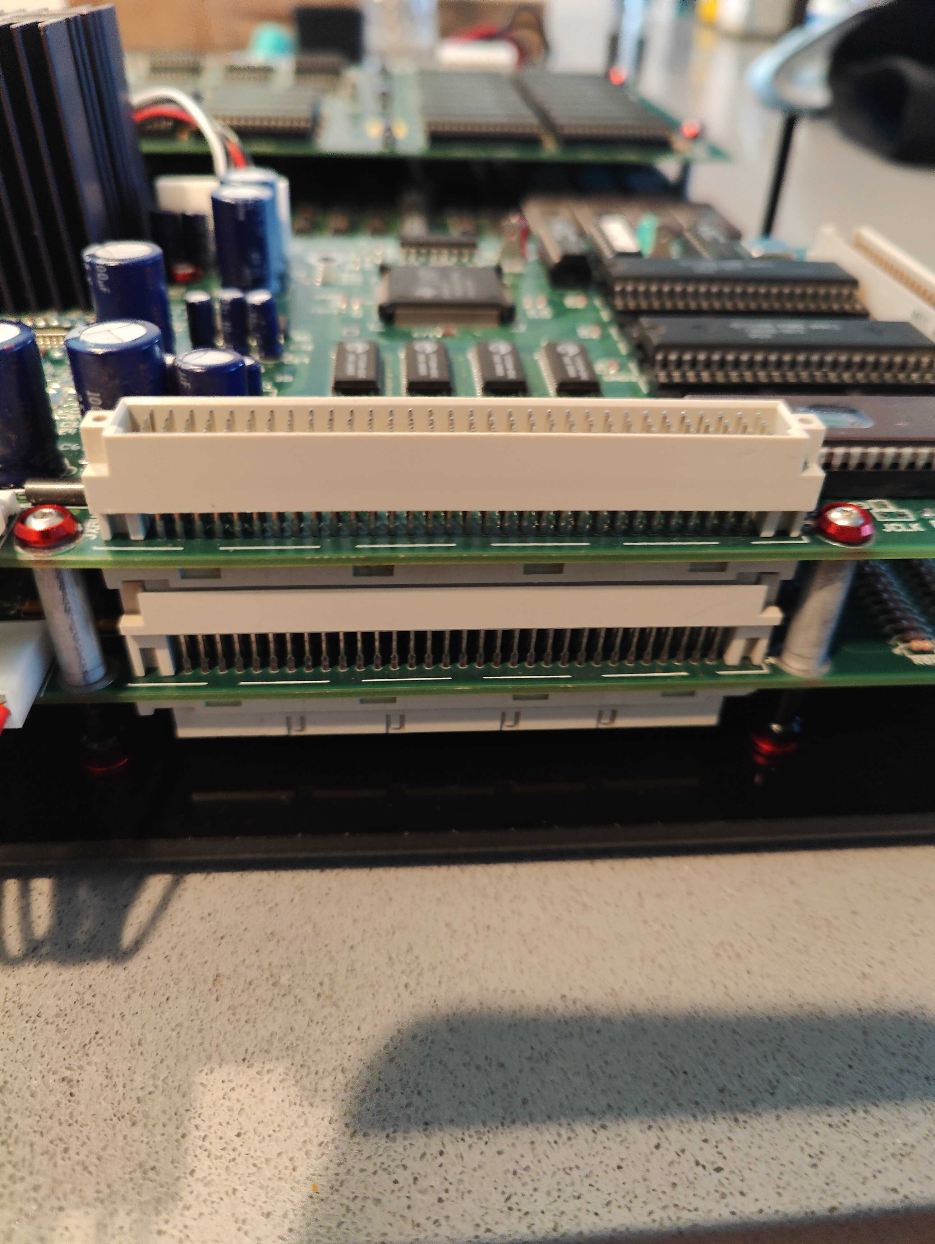
I'm trying to repair an arcade PCB with intermittent audio. The board on top is the audio board, the bottom board is the everything else.

There is a short or poor connection somewhere in this 96 pin DIN, press-fit connector.

I have OEM replacements, and would like to install new ones, but really have no idea how to do it properly (if you can even do it properly). My first thought was to do the following:

  • Physically cut the pressfit connection to remove the plastic housings
  • individually remove each cut pin from the PCB
  • 3D print a "frame" around the connector area to minimize PCB flex, and use an arbor press to insert the press-fit connector

If anyone else has suggestions, I'm all ears!

194


I'm trying to replace the jet engine fan inside the PSU of a Nu 1.1 with a Noctua equivalent and am having trouble identifying the connector. The PSU is a Delta Electronics Model EDPS-250AB A, Part Number 400-5494-91.

I have taken several pictures of the fan connector and its header in the hopes of identifying the connection. I originally thought it was a JST-EH 2.0, but it is not, and the only means of comparison that I currently have.

Photos here: https://imgur.com/a/JQVahV3

Please help!

195


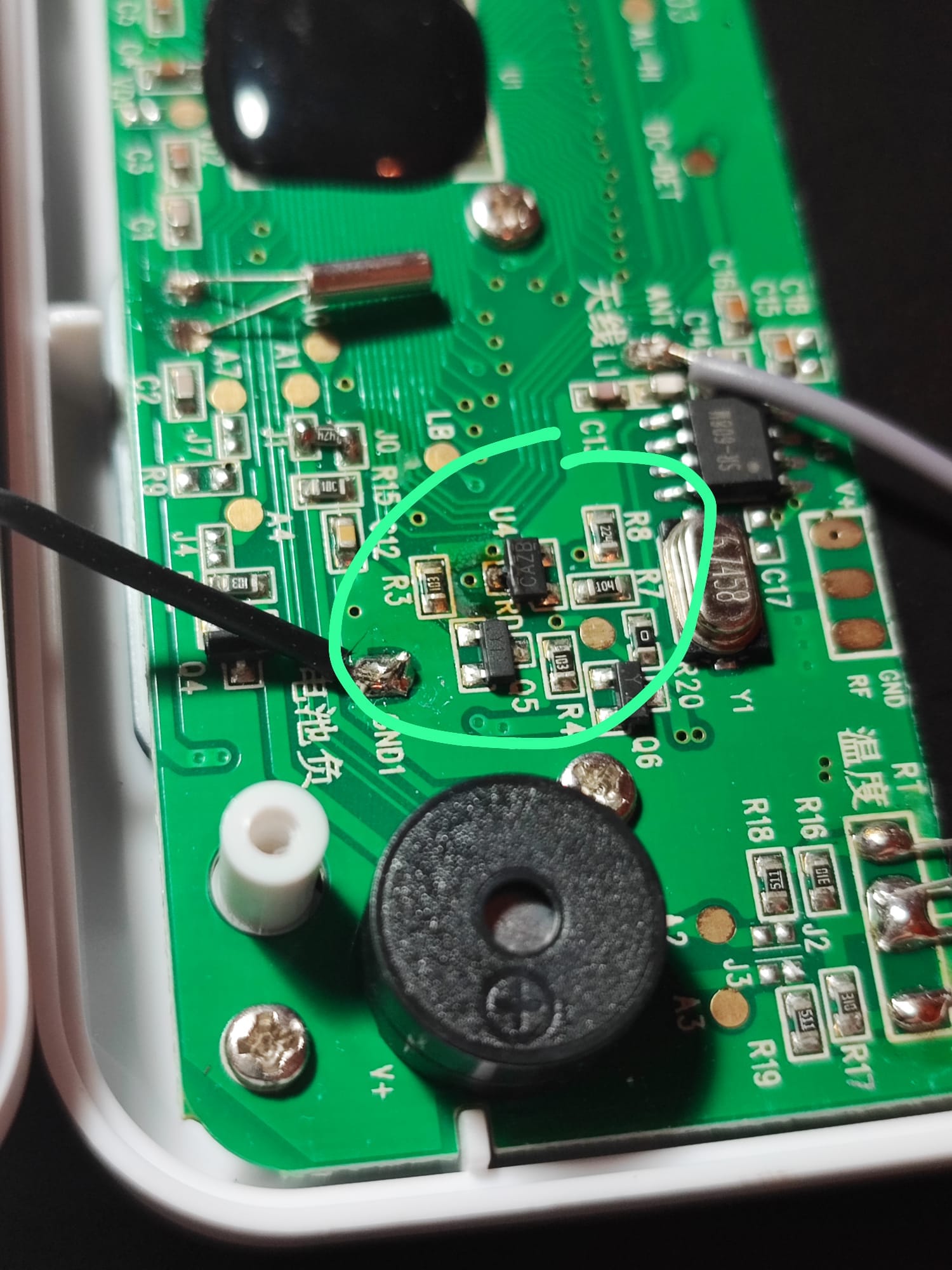
My room thermometer is consuming a full stack 3 AAA batteries in just 24 hours. I opened it and found that maybe the component circled in green is burnt (CAZB).

Can you please help me identify what it is in order to replace it?

Thanks!

196


I lost my electric fence tester, probably the pigs ate it. But I opened it once to resolder the earth wire and found it's really just a voltage divider with resistors and leds, so I can probably rebuild with stuff I have. What resistor values though? 2k to 10k V run through the fence. If any of you good people have a diagram, a formula or an idea, please help.

197


I wanna run a HR202 moisture sensor and an Arduino. Yes, I picked a HR202 to challenge myself to make it work. I already have some easier-to-use SHT40 in stock.

This sensor can only run with AC 1.5Vpeak max. So, I've created this little circuit to provide AC, and I'll only read it when the oscillator output is HIGH, so I can read it briefly at the same time with the help of Arduino's ADC. Could this circuit work? Thank you.

198


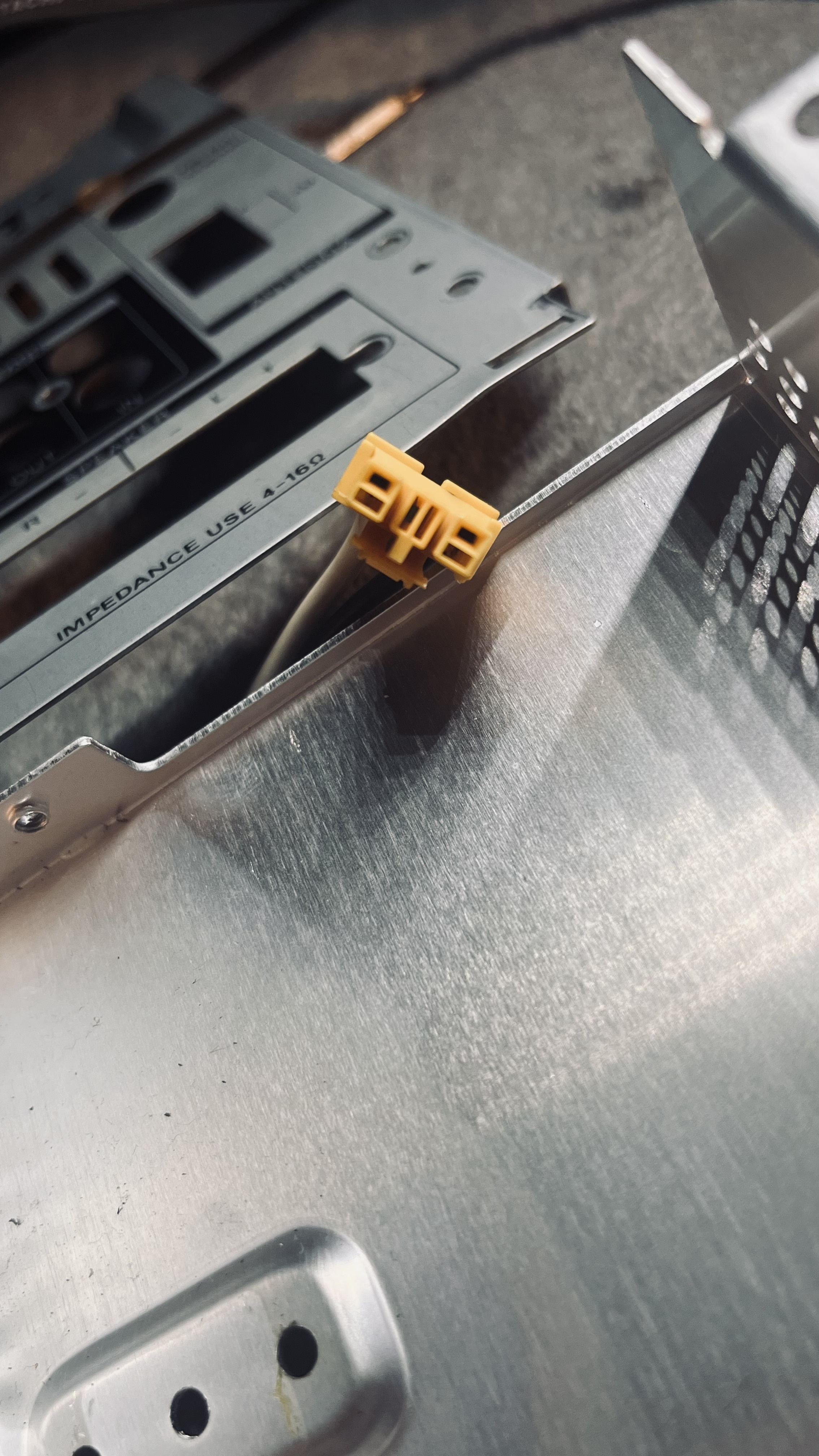
Here's a power cable from a Cmt-ex1 Sony CD player. This connector used to be connected to the inside of the power supply. However, I had to disassemble it because I needed to replace the motherboard for the CD player. I found this CD player at Goodwill, but the wire was poorly connected with a completely different cable. It was patched together using electrical tape and wire connectors. If there isn't any type of connector like this in the world. how could I Frankenstein it with another cable without it looking somewhat ugly.

The original cable was called E81093 (UL) NISPT-2 VW-1 105C 2X18AWG, C(UL) NONINTEGRAL SPT-2 FT1. Also the yellow plastic says Amp with a + on top of the M. this CD player is from 2000.

199


I want to use an IC that will take x4 3.0 PCIe lanes, and adds a USB 3.1 controller.

This ASMedia one looks ideal, but doesn't appear to be available to the common folk: https://www.asmedia.com.tw/product/E0CYQ4fSpaQxdjzA/f32YQ14SmApn1wNA

There's also https://www.ti.com/lit/ds/symlink/tusb7340.pdf - but that costs 22USD with LCSC, as well as being much slower (only using x1 lane)

I'm finding it hard to Google as well, because it seems to bring up complete products rather than ICs.

Can buy a whole card on eBay with the ASM3242 on it!

Can anyone help here please?

200


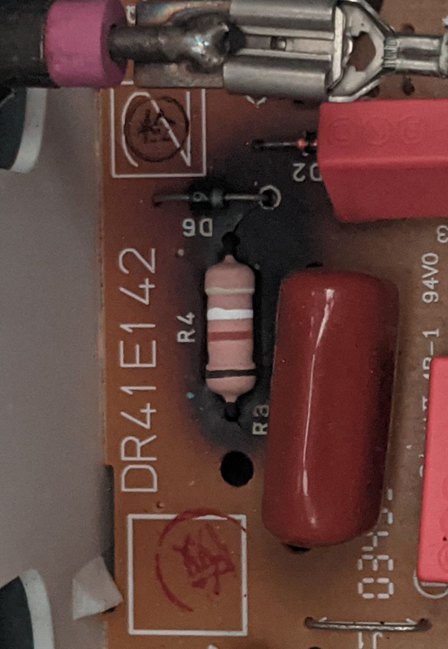
Mates bread maker stopped working so I had a look inside and saw this burned resistor.

I'm guessing the heat changed the colors a bit so wondering if anyone has experience in reading cooked resistor values.

I removed it from the PCB and measured it at 403 Ohms.

Thanks for any help.

view more: ‹ prev next ›