Ask Electronics

3772 readers
1 users here now

For questions about component-level electronic circuits, tools and equipment.

Rules

1: Be nice.

2: Be on-topic (eg: Electronic, not electrical).

3: No commercial stuff, buying, selling or valuations.

4: Be safe.


founded 2 years ago
MODERATORS
126


Does anyone recognise these power supplies? They're cheap AliExpress led drivers and I want to change its output voltage to around 22V from 12V. I've read that the way to do this is to adjust the REF voltage on the IC that controls it. It's a KA3845 but I don't understand where that reference voltage is regulated. One voltage is feedback from the output where then other should be a reference.

What would be the best way to approach this? I can't find any schematics on these boards unfortunately.

Thanks.

127


I have a 3D printer and have a special filter that has two 24V blower fans that are connected in parallel. Unfortunately my printer doesn't have the proper connectors for the fans. So if I purchase something like this power jack adapter I know the adapter is 12V not sure if that would make a difference. Anyway if I connect the female part of that adapter to the fan cables and plug in my laptop charger which is rated for 19v to 24V would that be ok?

If those adapters are fine, should I just purchase 12V blower fans instead?

128


Hi,

I recently bought a few pre-made amplifier modules for an 8-channel amplifier project (for a sound installation).

The amp is based on the TDA7294 chip and is rated 85W nominal. Now I'm looking for a power supply, but I'm a bit lost (this isn't really my strongest field, to put it mildly).

Do I just need to add up the output power, 8*85W = 680W, or could I get away with using something smaller, like a 300W or 300VA?

Also, the seller said that you need to use CV power supplies, CC won't work and kill the circuit. Does that mean a switching supply can't be used?

It looks like the module has a rectifier and smoothing caps integrated, so I could potentially just use a transformer, right?

Best, N

129


I have to fix a slightly very stupid mistake that I've made.

I'm trying to recreate the conductive lines of a membrane keyboard, unfortunately after trying to unglue them they got ripped off, I've painted 2 coats but it I'm receiving no signs of life from it.

Is Liquidwire the wrong paint for the job? Maybe the circuit lines ar too long to fix? Should I try copper or silver paint?

I've read online that shaking the pain is not enough and that I should also stirr it.

130


I have two led strips used for 2x27" monitor bias lighting. Each have their own USB cables for power. These two USB cables are plugged into a 2-port wall charger for a phone. I would like to use a 2x female to 1x male adapter to join the two USB cables into one, then plug it into a much smaller 1-port USB wall charger. The reason is due to my space constraints.

Will doing this impact its energy efficiency, ie using an adapter like this?

https://www.aliexpress.com/item/1005004340044483.html

131


Hi, I have built a microvawe transformer spotwelder, I have put a single turn of welder wire for in the secondary and I'm timing it with arduino. Worth mentioning it was/is a 230V transformer. Electrodes are sharpened copper rods. I believe the voltage is still high. The spotwelds it produces are slightly discolored and not as strong as you would expect. Is this design fundamentally borked? Is there anything else I can make to make it better? Photo from test stage before it was built into a project box, it is less "shocking" now.

132


Currently, only one company in the world -- ASML -- has the technological capability necessary for the creation of photolithography machines which are sufficient for the production of modern semiconductor devices. What I'm wondering is at what point does semiconductor manufacturing become practical, or even feesible for small organizations, or independents? One must be able to surpass the cost of the machines, and the resources necessary to manufacture them. I presume that a company like ASML is also extremely picky -- willfully, or by regulation, or otherwise -- about who they lend their technology to.


I'm not sure if this is the right community for this sort of post. Please let me know if not, and if there is a more suitable place to put it.

133


Hi!

I've asked Siglent support but after a couple of responses the thread went cold. Maybe I'm being dumb but I've noticed that there's a frequency (low, around 100Hz) where scope response changes a bit. Below and above it square input looks square. Right about it square input looks slanted.

I tried to do a very slow "sweep" and there's small but visible change in the envelope. So, e.g. with a constant 600mV p2p input lower frequencies measure exactly that while higher ones measure 612mV, so ~2% diff.

Terminated 50Ohm cables (not that it matters at such a low freq) to be sure. Latest firmware, after full self-cal. Siggen itself seems allright, I have an ancient Tek scope and the siggen output looks Ok there with same input/same cables. Scope seems happy and fully functional otherwise, few years old though, out of warranty.

Has anyone else seen anything like that? Is this a normal behavior within the expected margin of error?

Thanks!

134


Hello y’all! I’ve always been interested in computers and programming for as long as i can remember, but recently i’ve decided to try to get into some of the deeper stuff behind that, into the wonderful world of electronics. Where should I start? What courses or books or youtube series should I consume? What are some high-quality forums, communities, blogs, etc. to learn from?

135


I'm working on an Arduino project that will likely rely on a 9v for its power. If I can get at least 40 hours of power, I'd be happy with that. Here's why I think it's doable:

First, rechargeable 9v lion batteries nowadays have substantially higher capacities than even a few years ago. I see one on Amazon rated for 5400mWh!

Of course, I'll want to reduce power consumption as much as possible, so I'm thinking an Arduino micro would be the best choice (though I will be attaching a shield to it, which will add to the current draw.

My understanding is that the linear regulator on the Arduino is capable of reducing the 9v down to 5v, but at great expense to efficiency through heat loss. My thinking was to bypass the linear regulator entirely, and rely on a much more efficient buck converter to adjust the voltage down to 5v.

Thinking it might be possible to reduce the core clock as well, and run the Arduino at 3.3v instead of 5.

Anything I should consider that I might have missed? I'm excited for the project, but definitely need to get the power consumption as low as possible so I can run it off a 9v and not be constantly swapping/charging.

136


Hey folks, I have a Mackie 802-VLZ4 mixer which does this narsty pop when you turn it on; I'm pretty sure it's what killed one of the woofers in my monitors. It has been put out of service and I will either harvest its many through-hole organs or else fix it.

I could not find a schematic, but I don't assume it can't be found, I just haven't yet. It's not a big board but it's all analog from what I can see.

There appears to be a separate power supply board which feeds

+15 AGND -15 GND +48

to the mixer, which is two boards connected by thick soldered wires.

I have looked with magnifiers on at all the caps, none appear to be leaky or swole, but I'm assuming this has something to do with the power supply putting out a spike at power on. The power board has a lot of really tiny caps, I still don't really understand power supplies that well. I need to do more studying of them I suppose, they're pretty central.

Edit: I have a little tiny oscilloscope that I bought years ago and haven't used yet, just figured the day would come. This is probably that day, to measure that spike from the power supply. From the looks of it I'm pretty sure that if I can just get better quality, non-spiking power to those connectors it should be fine.

Anyways this board would be very handy right this second if I felt like it was safe to let it touch my good kids, but at the moment it's the unfavored child who won't stop hitting the others. If anyone would like to see them I have/can take photos. The boards have codes on them, presumably codes that Mackie employees could use to dig up schematics, but will they? I suppose I'll try to find out today. It's past warranty of course.

137


So I'm a refrigeration tech with some electronics manufacturing experience. But I've never combined the 2 skillsets so I've been toying with the idea of building a large vapor chamber to cool a computer via direct immersion in a refrigerant. I know its about as far from practical as you can get but it sounds like fun.

Ignoring all of the many many other problems with doing this for now the one thing I'm not sure about is how well the electrolytic caps on the various components would survive. I would need to pull a fairly hard (500 micron) vacuum on everything before I charge it with refrigerant. I know most electolytic caps aren't vacuum rated but I'm not sure if that just means you can't have them operating in a vacuum or if they will immediately pop if you just subject them to hard vaccum period. Additionally while I am planning on using a low pressure refrigerant (probably some R-123 substitute but I'm definitely still working on that part) the components would all still be subject to pressures of up to about 20 PSIG at the high end. Beyond that point I would probably have an active cooling system kick in just for safety sake. I'm not sure how well the caps in particular would survive being immersed in a liquid under 20 PSIG pressure.

Does anyone here have any experience subjecting electrolytic capacitors to hard vacuum or elevated pressure? At what point do they just pop?

138


My project is a "breathing" white 12v LED strip controlled by an esp32 on a dev board, and switched with an IFLZ44N mosfet.

In my video you can see it working but also hear the power supply complaining.

I'm using the LEDC Arduino library which allows me to select the frequency and resolution for PWM.

If I set the frequency too low the whine is extreme, but at this setting it's the best I've been able to achieve, which is about 9000Hz. Unfortunately you can still hear the sound from across the room!

It is a cheapo solid state power supply that claims it can output 12v up to 25A. I tried my desktop supply and it emits some whine too, so I don't think replacing the power will totally fix this.

Is there a technique for tuning the frequency or even just masking it somehow?

139


I have some metal film 1/2w 2.2ohm resistors in some car wiring. I'm concerned about the durability of this install and am seeking advice on how to protect the resistor once it's soldered in place. The obvious is heat shrink tubing, but it's there anything more substantial?

I'll be using these resistors in a custom pigtail that will plug into the car wiring. 3D printed housing? I have tried searching and I haven't found anything like that.

140


Hello! I bought 30 simple UV leds (those with a big and a small leg, not a single strip). I'm trying to build a UV station to dry my resin but idk how to proceed. I tryed watching some videos but there is a lot of math to build that and I can't do it. I have 30 led lights, 5 resistors of 100 and 5 of 300. I wanted to use AA batteries. Do I need 8 of them?? Its not going to be turned on for long, just some 30 seconds at a time.

Can someone help me?

141


I'm trying to use an RPi Pico W as a temp/humidity sensor using a DHT20.

It kind of works - at least sometimes, but I keep "losing" sensors more or less randomly.

I connected everything up like here (using MicroPython): https://github.com/flrrth/pico-dht20 There are currently 4 sensor-boards, 3 soldered, one on a breadboard.

The error modes I could observe are:

  1. DHT20 fails to init - sometimes after the first read, sometimes after days. Resetting the machine works sometimes, if not, power cycling usually does the trick

  2. The board just "stops" after about 5min - the serial console just says "device disconnected". Power cycling is the only option.

My measurement work by having a timer fire every minute, connect to wifi, read from the sensor, and then send an mqtt message (either the values or an error message) and shutdown wifi again.

My current ideas why it could fail (but I'm not an electronics guy at all):

  • There is some kind of "rogue current" messing with some IC.
  • Some component is broken
  • Maybe the power draw is too low or issuing sleep() messes with the USB-power connection somehow?

For me the problem is, I don't really know where to look for errors. The software works in principle, the soldering seems to be good enough to sometimes work for days, and looking too deep into the whole electronics side is beyond my capabilities.

142
9
submitted 2 years ago* (last edited 2 years ago) by irdc@derp.foo to c/askelectronics@discuss.tchncs.de


I've recently acquired an uncalibrated Philips PM2534 (edit: the battery-backed factory calibration data was lost due to the battery running out). I'm looking into somehow getting it calibrated. However, the calibration procedure is rather involved, and requires such things as an exact 300V DC (the service manual recommends using a Fuke 5700).

Anybody know of a way to have this multimeter calibrated? I'm a hobbyist and don't really need such things as traceability and certificates.

Edit: I live in the Netherlands.

143


I want to change te battery setup in the camper van a bit.

Currently there is a single battery which is charged by either solar, engine or 230v. Then a transformer to 230v to power the outlets.

The idea is to add an extra battery. A lot of people are saying that it isn't a good idea to put those batteries in series or parallel if the batteries are not exactly he same. Now our idea is to switch between the two batteries with the help of some relais and an Arduino or something. So then + of both batteries would be connected to a relay and after the relay we can connect them together. Is this a good/safe way of doing that? Or will we be running into issues that I'm not seeing.

Thanks in advance!

144


Hey friends,

I have a two daisy chained shift registers (74AHC595) which are controlled via an ESP32. I want to set one output to high at a time before switching to the next.

The code seems to work, but the outputs O_9 and O_10 are not staying high (zoom) after setting them, whereas all the other ones are working fine. This is the used code snipped:

pinMode(SHIFT_OUT_DATA, OUTPUT);
pinMode(SHIFT_OUT_CLK, OUTPUT);
pinMode(SHIFT_OUT_N_EN, OUTPUT);
pinMode(SHIFT_OUT_LATCH, OUTPUT);

digitalWrite(SHIFT_OUT_N_EN, LOW);

uint16_t input_bin = 0b1000000000000000;

for(int i=0; i<17; i++){

    byte upper_byte = input_bin >> 8;
    byte lower_byte = input_bin & 0x00FF;

    digitalWrite(SHIFT_OUT_LATCH, LOW);
    shiftDataOut(SHIFT_OUT_DATA, SHIFT_OUT_CLK, MSBFIRST, lower_byte);
    shiftDataOut(SHIFT_OUT_DATA, SHIFT_OUT_CLK, MSBFIRST, upper_byte);
    usleep(10);
    digitalWrite(SHIFT_OUT_LATCH, HIGH);

    delay(10)
    input_bin = input_bin>>1;
} 

Is there anything I'm doing wrong, or any idea on where the problem may lie? I've already tried looking for shorts and other error sources, but the design was manufactured on a PCB and no assembly issues are noticeable.

145


The lower part of my screen is updated one frame earlier than the upper part. I was able to isolate the error to the HDMI output of my laptop. The screen or cable is not broken, as I don't get these errors with other connected devices. I am assuming it is some hardware defect. Does anyone know what it could be and how I could fix it? Here are a few pictures that show the problem: pixelfed

Solved: Ok, it seems to have been a software problem. That had to do with the sync. I have installed ubuntu on the laptop for now and everything works again. Some update seems to have shot something. I am now using a LTS version.

146
4
submitted 2 years ago* (last edited 2 years ago) by Froghut@lemmy.dbzer0.com to c/askelectronics@discuss.tchncs.de


I'm trying to build a esp8266 weather station and got some MCP1700-3302E to power the esp8266 from a lipo. But when I connect the lipo to the MCP1700 (looking at it flat spot at the front, ground left, Vin in the middle and Vout on the right) I get no output at Vout. I googled and could not find anything. I tested 5 different ones and it's the same for all of them. Could I just have a batch of broken ones? Edit: attached a picture of my very simple test setup Edit 2: I just connected three lipo directly to Vin, that seems to work without any problems (at least for a few days now)

147


Questions:

  • Can you test 450V high ripple current caps with a any old desktop RCL meter?
  • Has digikey shipped me faulty units?

Background:

I've gotten a couple of 660uF (not a typo, it's some weird high ripple current caps for an outdoor AC unit) 450V caps to replace some that I decided were duds. Normally I only measure components when troubleshooting, but this being 20USD with vat devices I thought "what the heck, I better".

The caps in question are chemi-con EKHJ451VSN661MA59M https://www.digikey.dk/en/products/detail/chemi-con/EKHJ451VSN661MA59M/17728502.

Method:

I'm using a Phillips PM6303A, which is a 1kHz RCL meter. Ambiant temp is approx 15°C. The caps have a 20% tolerance, so capacity should be >528uF, but when measuring both caps settle at approx 450uF after a little while. After 16hours it hasn't deviated for the one cap I've left in over night. The dissipation factor, tan(δ), settled at 0.57, while the datasheet states that it shall be no greater than 0.2.

For comparison, the caps I thought was faulty, have been running for about 20years, with the same specs, but came out to 550uF and 0.3, and as the spec said 0.2 I decided to change them.

148


It's the handle of a water kettle. Behind the circuit board is nothing. There is also no other circuit board in the kettle. Is the yellow thing the beeper? Thanks for any help 🙏

149


Hi, this post is structured similarly to r/PrintedCircuitBoard 's review request format. Since we don't have any PCB communities over here yet, I thought that this might fit in here and can maybe spark some friendly discussion.

This is a relay board controlling electrically driven windows and blinds. For this purpose it has some additional connectors to a weather station, interior sensors and an LCD screen.

It is replacing a ~20 year old board that has started to develop some annoying quirks. I've mostly copied what the original board did and adjusted it for the ESP32. This is not a production board and if all goes well, I will only ever assemble a single one of these.

The primary usage scenario is that the MCU will monitor the weather station and then actuate the motor groups (M1 - M6 connected on J3 - J8) to keep the indoors temperature and humidity in check.

At least during summer time the board will likely run 24/7 and will hopefully be used for a number of years. For maintenance reasons I've tried to keep it simple and the component count low.

Mains power is supplied from J1 and being fed to the motors via the relays. PS1 converts the line voltage to +5V DC for the relay coils and some auxiliary components. The switching regulator U2 steps that down to +3.3V for the MCU U1 and IO Expander U3.

The board size is mostly constrained by the preexisting mounting holes which gives me plenty of space to work with even with just a 2 layer board. The enclosure containing the mounts is installed indoors and is finger-pokey-tight.

Jumper JP1 allows me to supply the MCU devkit daughter board with +5V, should I ever replace it with a different one. Similarly J11 exists for future expansion.

J10 mounts another daughter board (not included in review) facilitating communications with the weather station. Should the station ever need to be replaced I can swap in a new, matching board.

There aren't any high-speed connections on the board. The fastest one is likely the SPI connection to the LCD controller but I can slow it down in firmware if necessary.

Regarding the DNP components: There are only 5 motors installed at the moment so I will cover the sixth slot with a piece of plastic for now. R1 and R2 will only be populated if the 10k pullup resistors integrated into the MCU are insufficient for typical baud rates.

While it is not the first board I've designed, it is the first one carrying mains power (European grid 230V@50Hz). I'm using 2 oz copper to accommodate the motor currents within reasonably wide traces.

In case anyone is interested, it will be running the ESPHome firmware to easily integrate with the Home-Assistant smart home solution. This also pushes firmware maintenance from me onto the ESPHome devs.

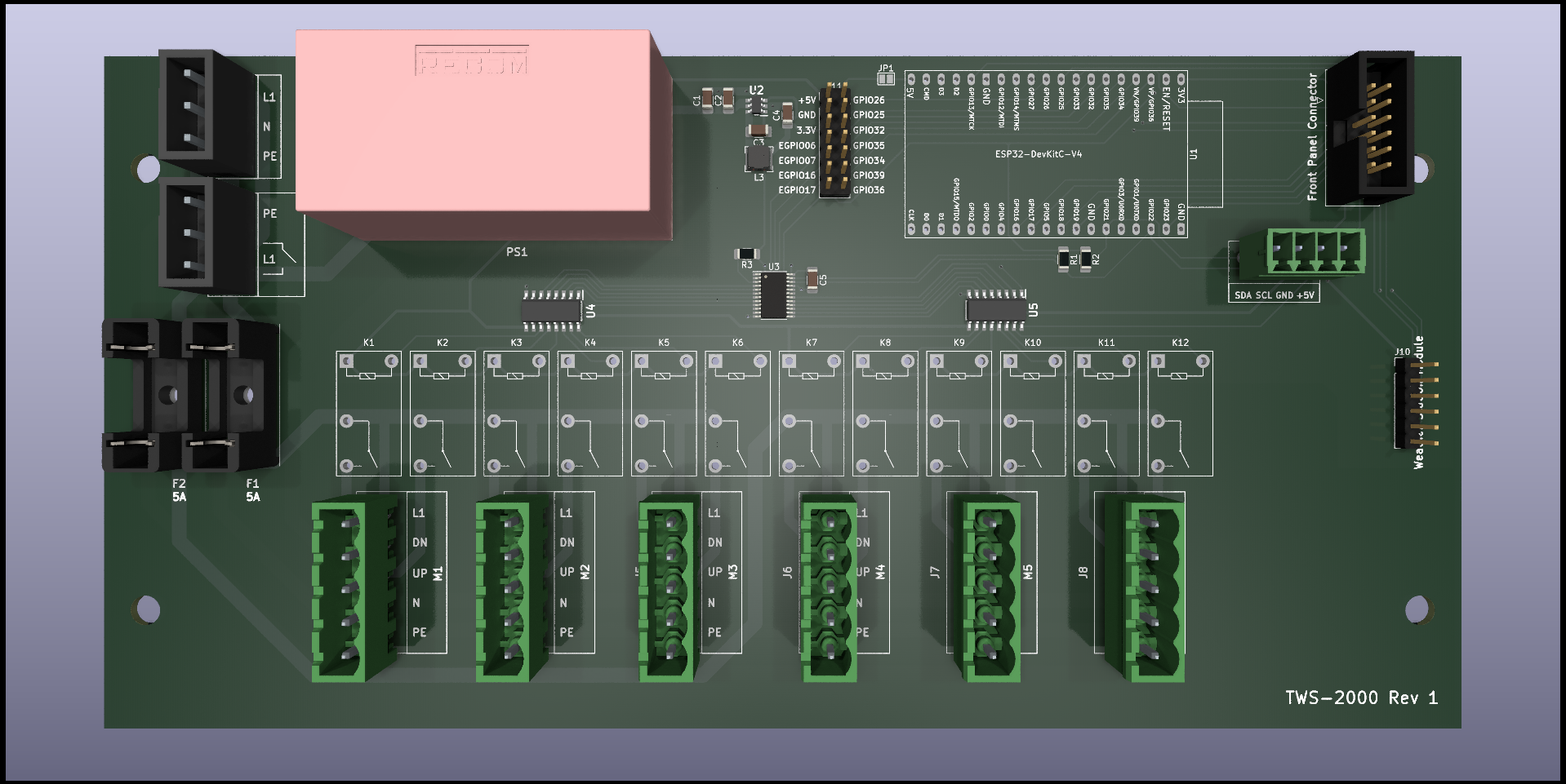
3D render from front (no 3D model for relays K** and MCU board; 3D model for J1 and J2 is a stand-in of same outer dimensions): 3D Front

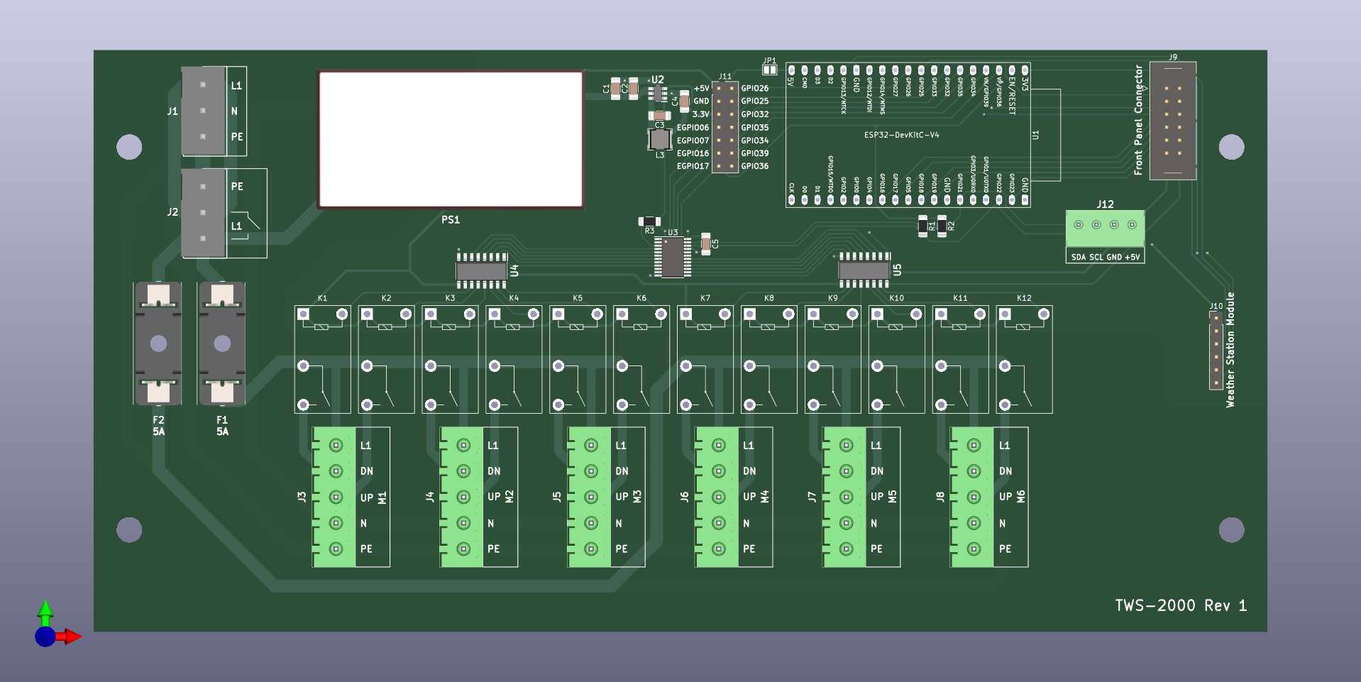
Orthographic view from front:
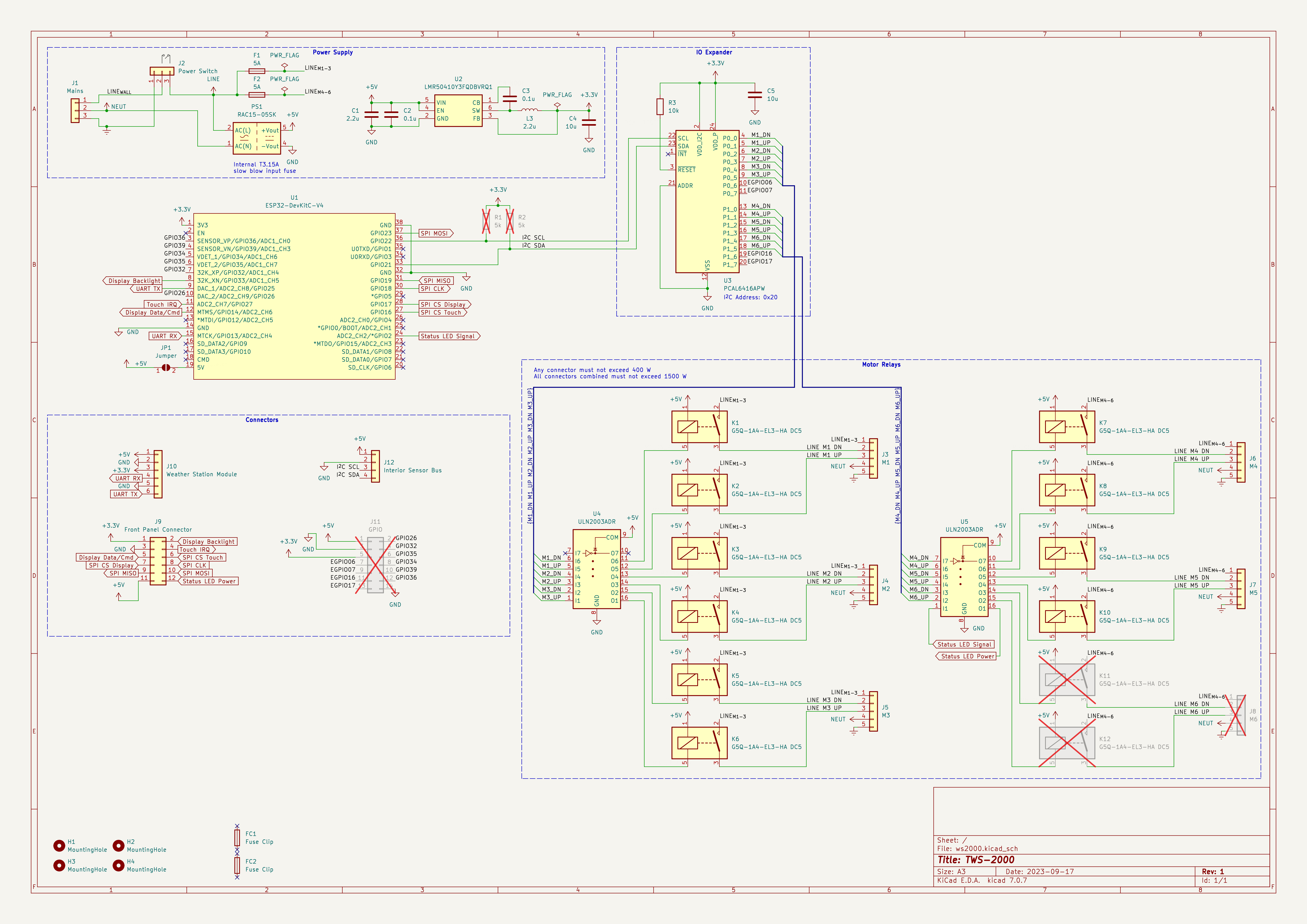
 Orthographic Front

Schematic:

Schematic

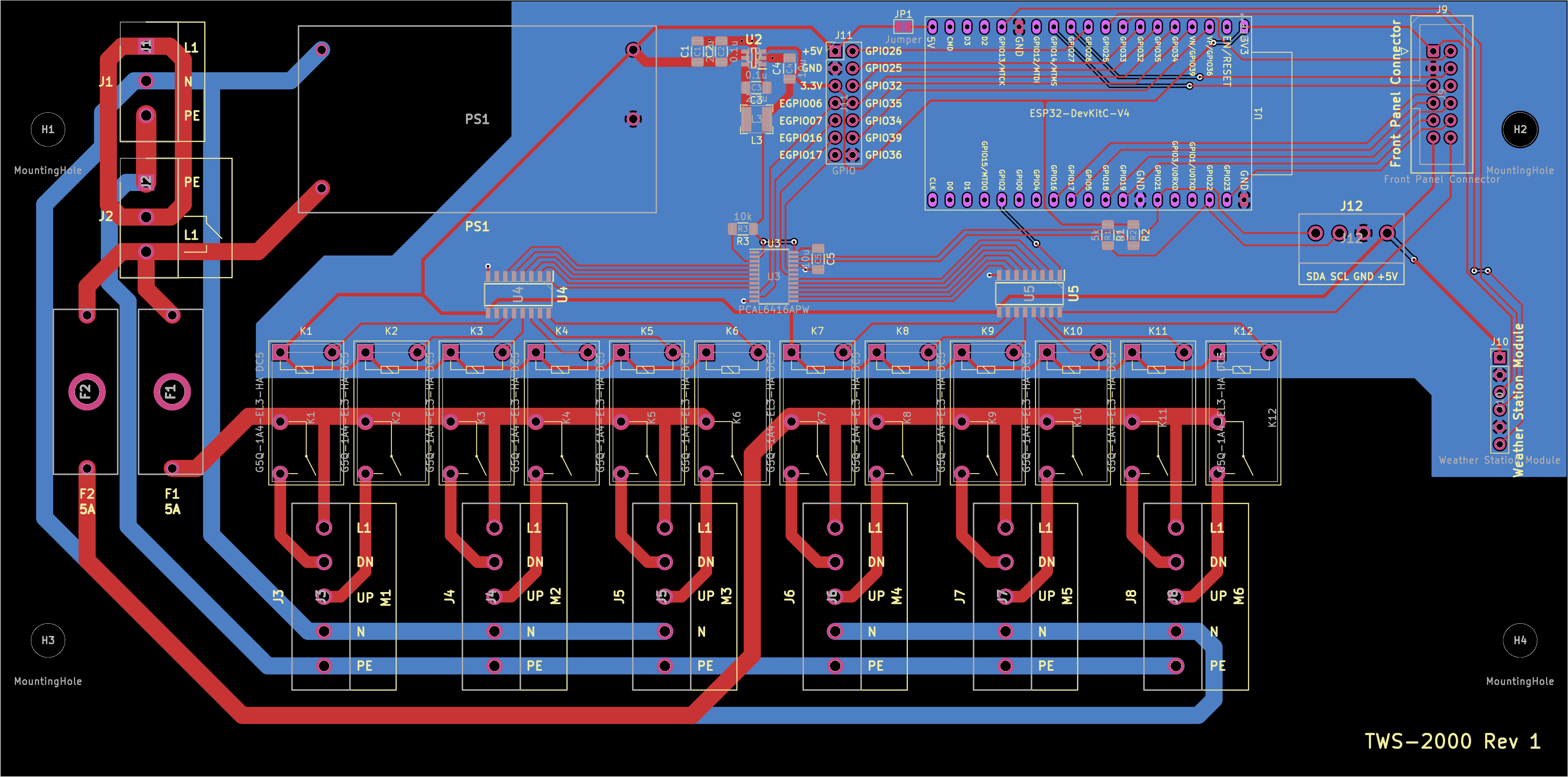
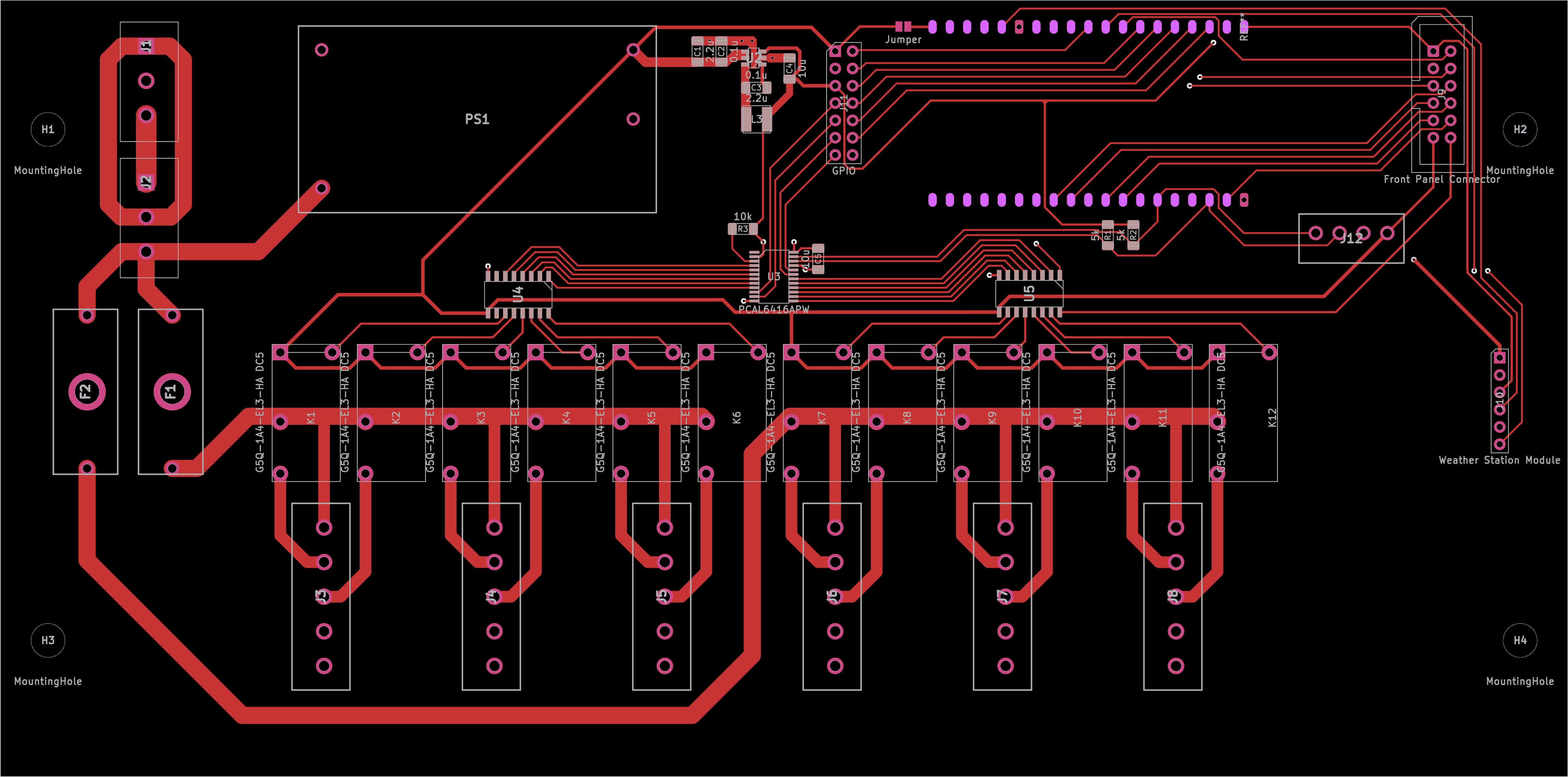
PCB All layers (For reference: thickest traces are 2.5 mm / ~98.4 mils; thinnest traces are 0.25 mm / ~9.84 mils): All layers

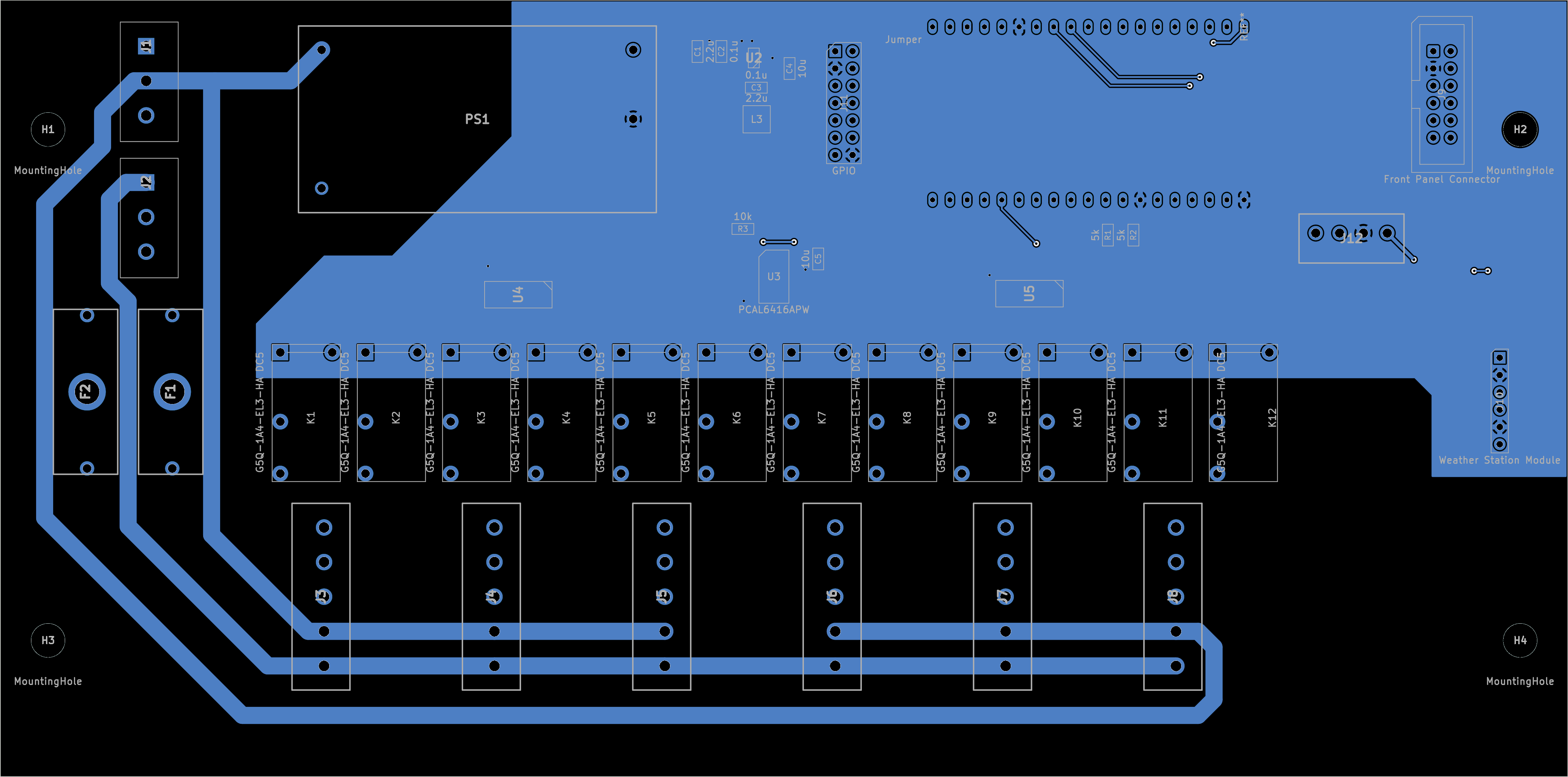
PCB Front layers excluding Silkscreen: Front layers

PCB Back layers + Front Fab layer: Back layers

150


Solution: @DJPhil@discuss.tchncs.de has made some really insightful comments below, which are really useful. ~~If you just want the cap you can set the parametric searches for 660uF, or in September 2023 I've found that digikey stock(s/ed) chemi-con EKHJ451VSN661MA59M~~.

Update 2: Turns out that EKHJ451VSN661MA59M is not the ordering code you'll want. That would be EKHJ451LIN661MA59M which returns 0 results when you Google it, or maybe a single result in a few days linking to this thread. So it looks like you'd be better off just getting some 680uF with blade snapins instead and retrofitting the board if possible. Just make sure it can handle the ripple current. Always check ordering codes twice my friends!

Original post

I need help identifying the terminals on some strange caps found in an AC inverter main board. The reason I state the AC part, is that the only other mention I've found of this layout, was a question on digikeys forum regarding an AC inverter https://forum.digikey.com/t/can-t-find-the-right-terminals-for-a-capacitor/19332 The capacitor in question has the same measurements as the one in the link.

In my picture on the right you can see the layout of the terminals, there's room for three caps, but only two was mounted, hence the relatively clean pads. On the left is one of the two caps in question. It says nichicon LQ(K), 85°C. Nichicon has discontinued the LQ-series, and the datasheet doesn't mention a 660µF variant. I don't know what fujitsu did to get caps with capacitance outside the E24 series.

Question: What is the name of this type of terminals? And more importantly: where can you get 680µF 450V caps with them? I haven't found them on neither Farnell or RS-Online.

For the sake of people googling this in the future, the AC in question is a fujitsu AOYS09LDC and the board was marked K05CM-C-A(03).

view more: ‹ prev next ›