226
Ask Electronics
3772 readers
1 users here now
For questions about component-level electronic circuits, tools and equipment.
Rules
1: Be nice.
2: Be on-topic (eg: Electronic, not electrical).
3: No commercial stuff, buying, selling or valuations.
4: Be safe.
founded 2 years ago
MODERATORS
227
11
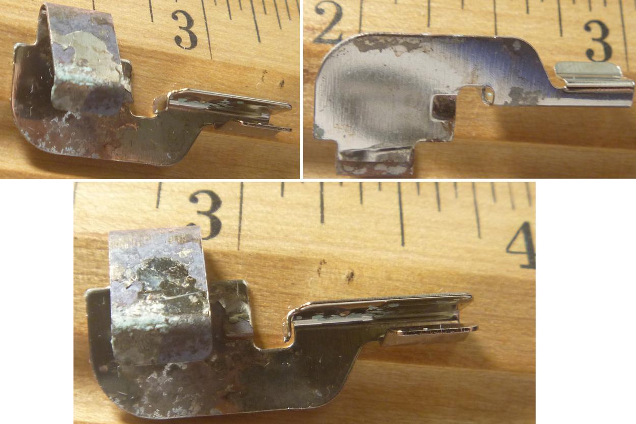
Is this one-piece battery-to-PCB "clip" standard (for easy replacement) or a custom piece? +PCB pad ?
(discuss.tchncs.de)
Hello,
No formal training, but do like to repair devices at home (and keep vintage electronics and computers going).
Yet another alkaline battery has leaked prodigiously into a device (after only a few months). A wall-mounted thermostat.
Is the sort of clip pictured, which contacts an AA battery negative terminal at one end, and seemed to just clamp onto a conductive trace at the edge of PCB at the other, an easy-to-find standard form (for replacement) or a custom piece?
It is quite corroded and even peeling, and suspect replacing the clip would be better than devising a work-around.
Visually searching through product photos on supplier websites (like Digi--- and Mous-- here in the US) has not been effective.
Thanks for any comment.
228
229
I got it with https://sabrent.com/collections/hard-drive-accessories/products/ec-ch2b. But since I bought it in EU, it has that charger. Is there no alternative other than buying a whole new charger?

230
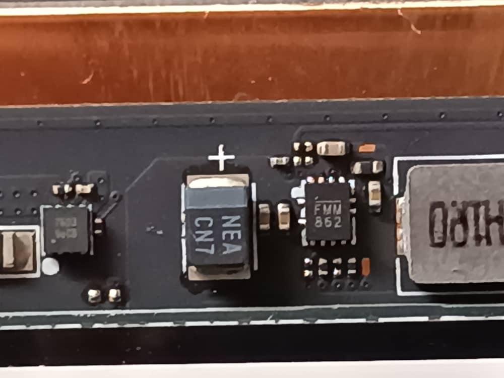
i can’t find ANYWHERE this ic chip, not even in chinese online stores. code is FMM862, laptop model is a Gateway GWTN141-10. it can also be another one that works. thanks in advance.
231
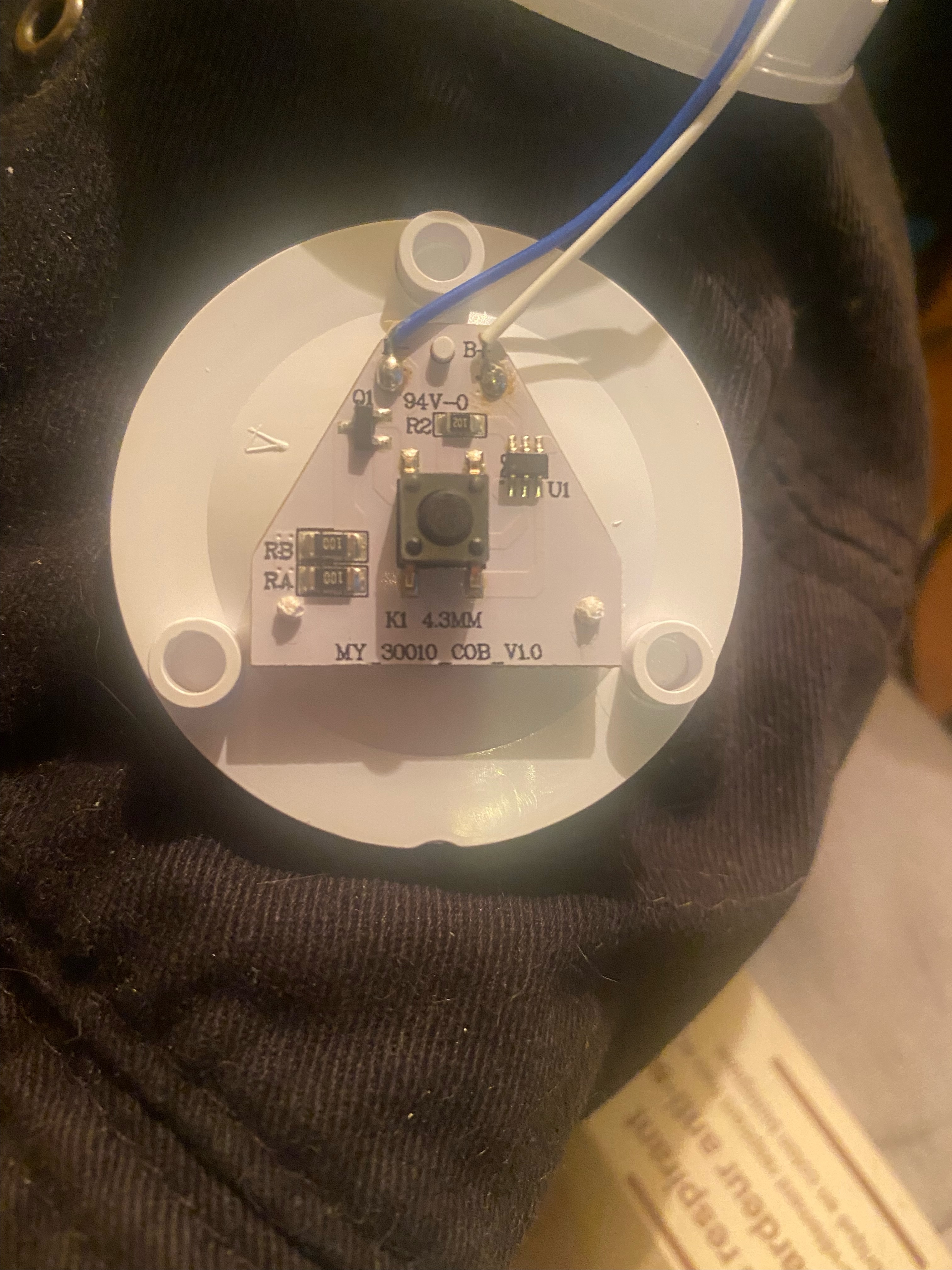
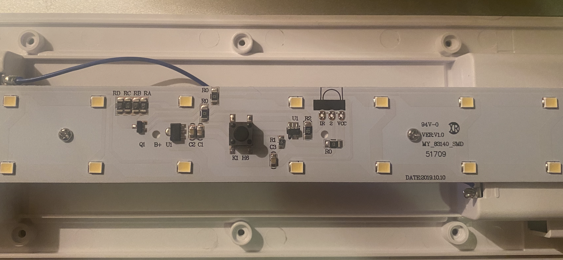
Hi all! I recently purchased some push-lights for my kitchen from my hardware store, and I stupidly didn't read the package that said that they shut off after 30 mins. This is super inconvenient in my dark kitchen, and I can't return them. I figured I might as well tinker with them, and any help would be greatly appreciated. The first picture is the small, round push-light (it was in a 3 pack, so I've got room for error with these), and the second picture was the even bigger disappointment because it's a larger strip light.
I found them online for reference here and here. It doesn't say they shut off in the description of these, but it says it in the user manual under "product guides and documents" for the rectangle light.
TL;DR: Help me bypass the "power saving" mode that shuts these off after 30 mins please!
232
233
234
Looking to replace the male connector in this picture. Any idea what it is called and where I can get it? I'm in Germany.
235
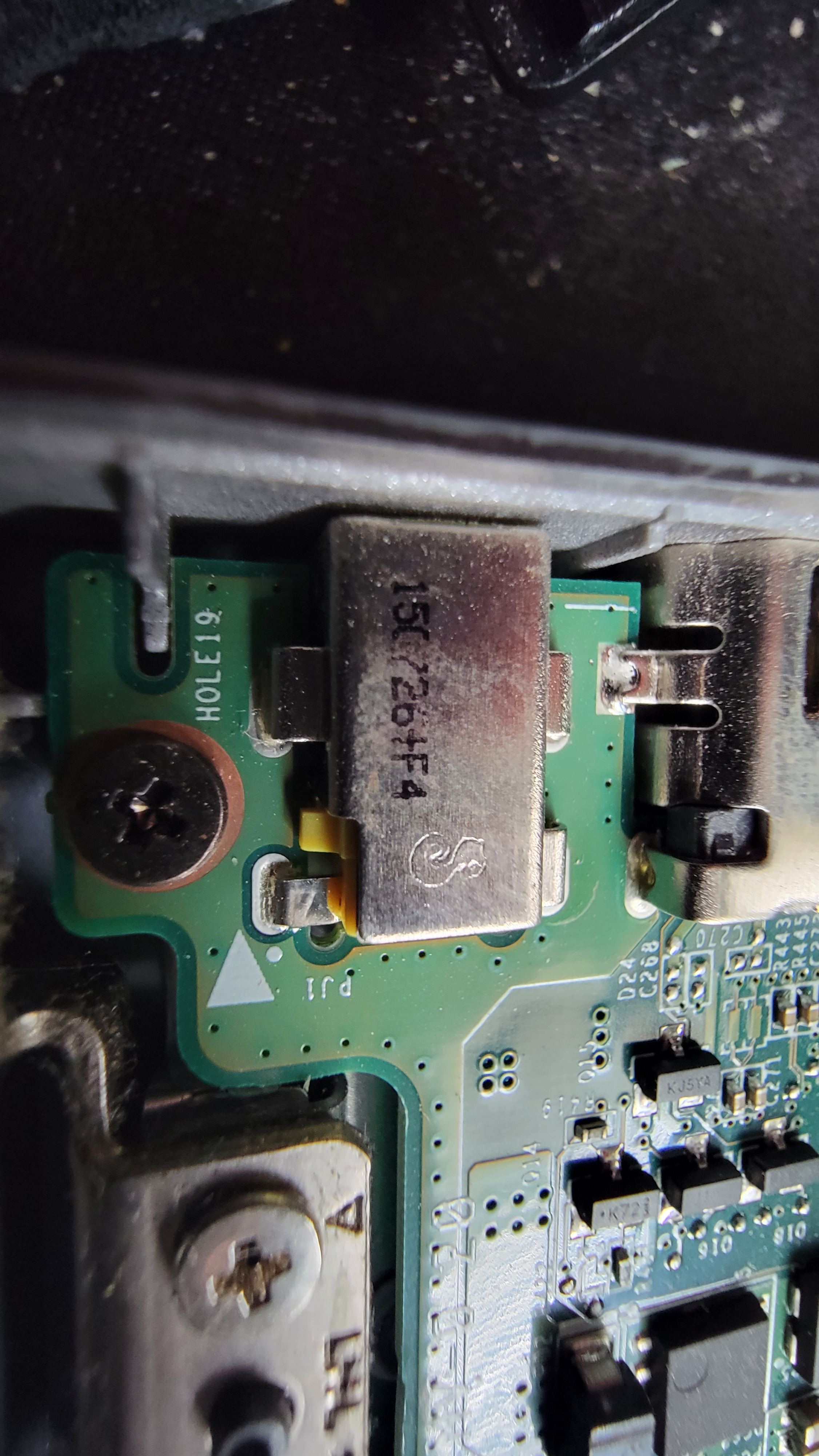
I have a acer c740 chromebook that has a cracked charging jack hoping I can find replacement part for it. Picture attached shows what's left of some number on it I think it's 150726+F4 not sure what the symbol is. The male end end is 3mm od 1.1mm Id if that helps.
236
237
238
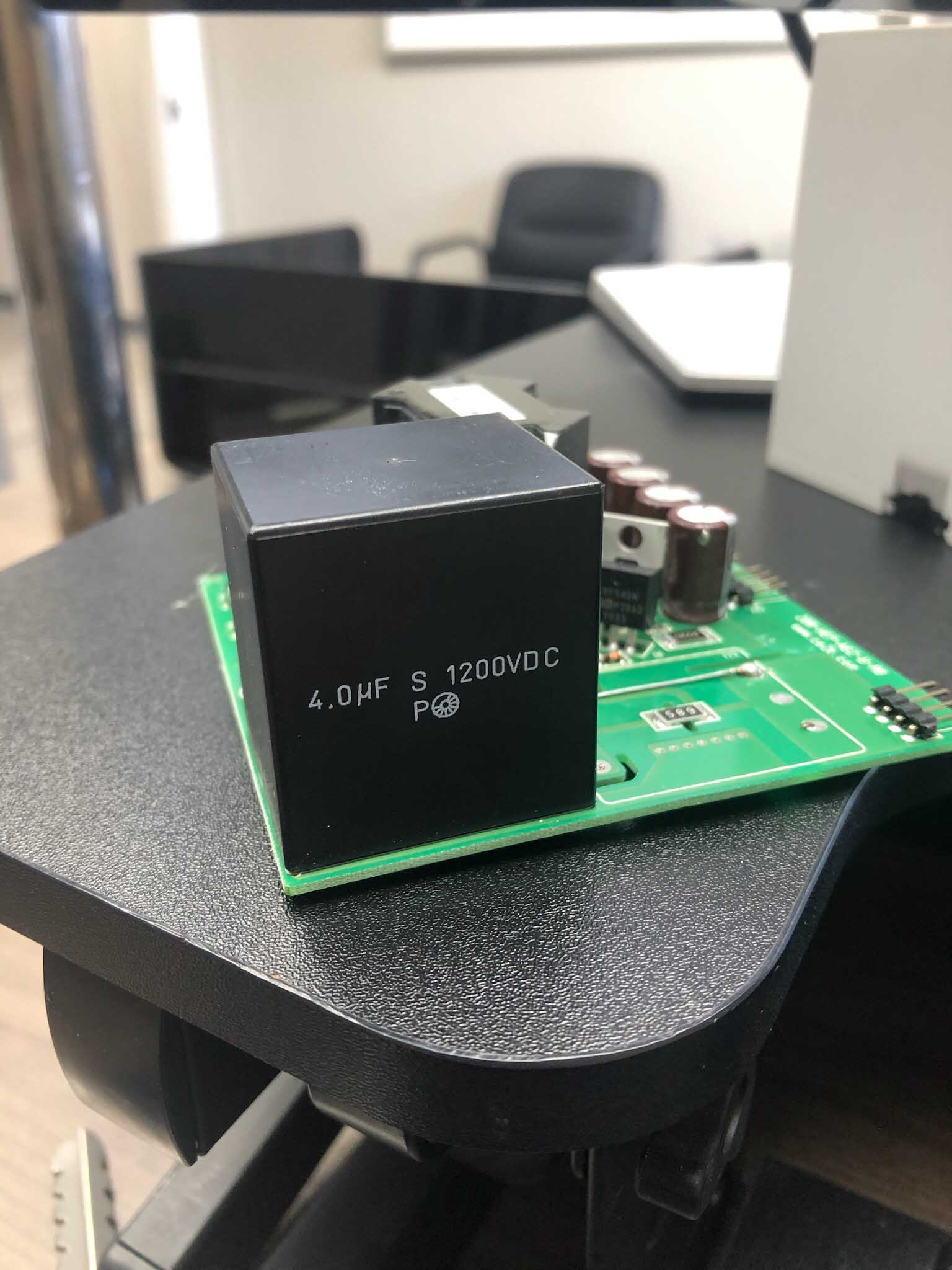
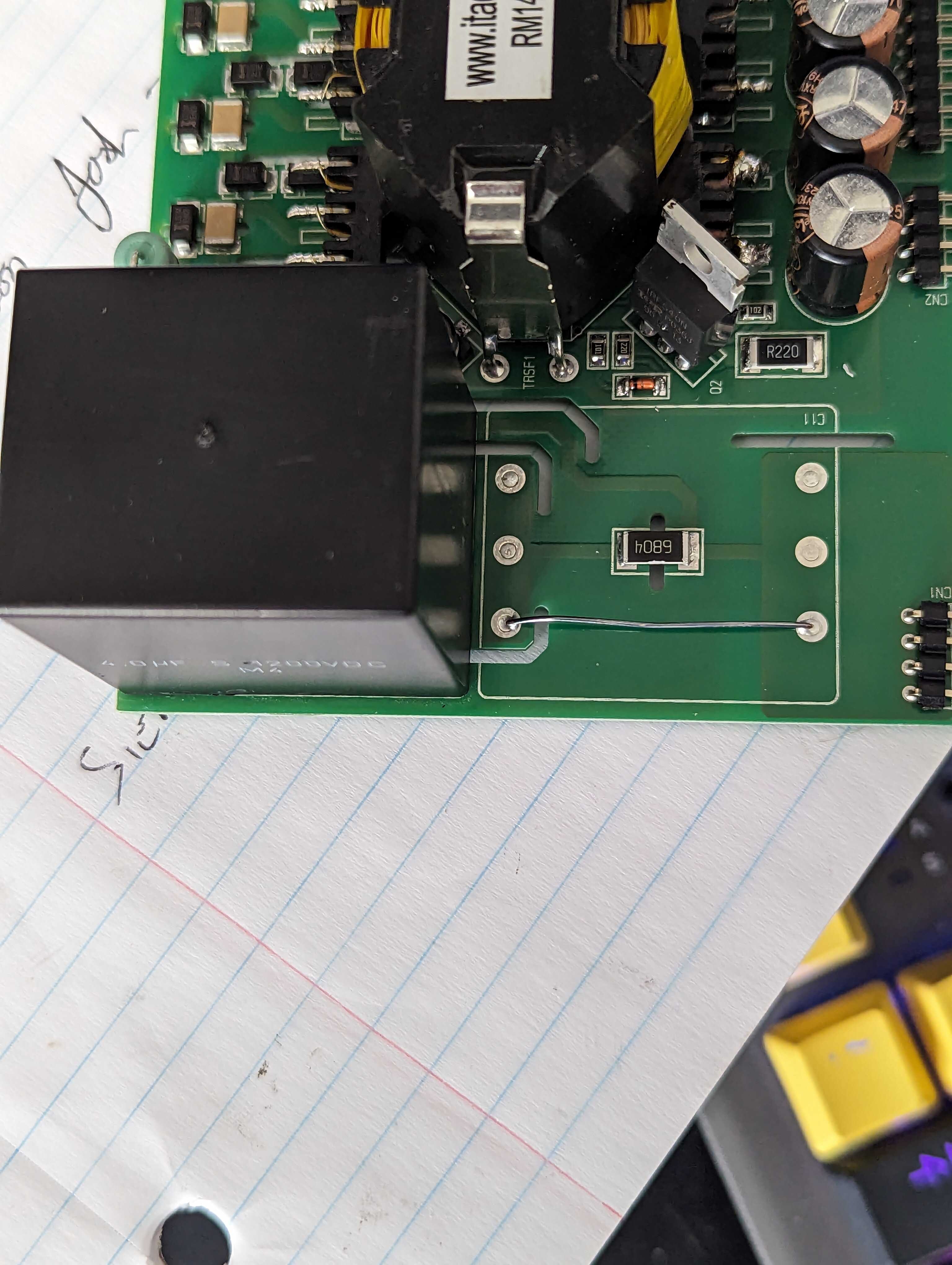
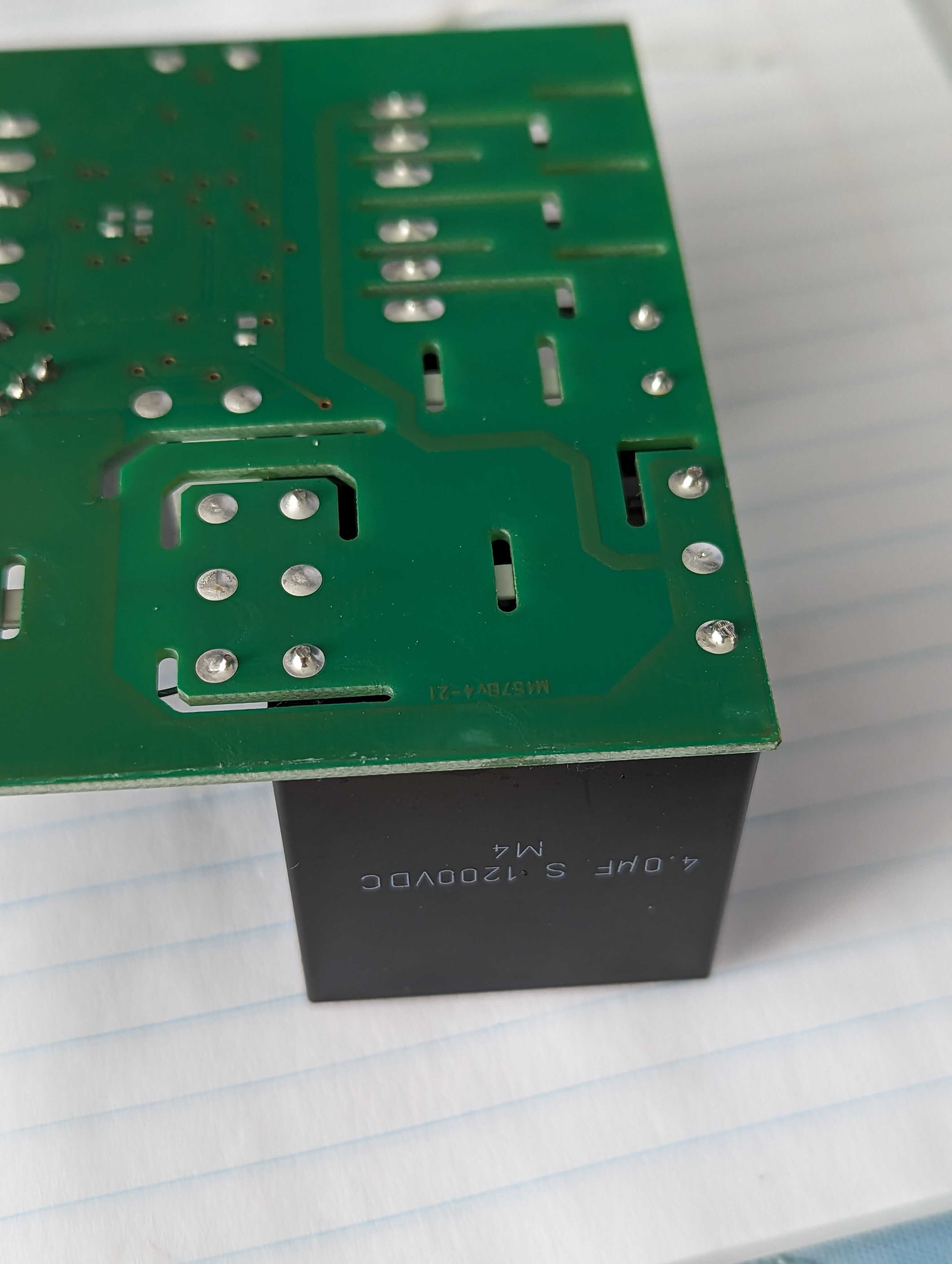
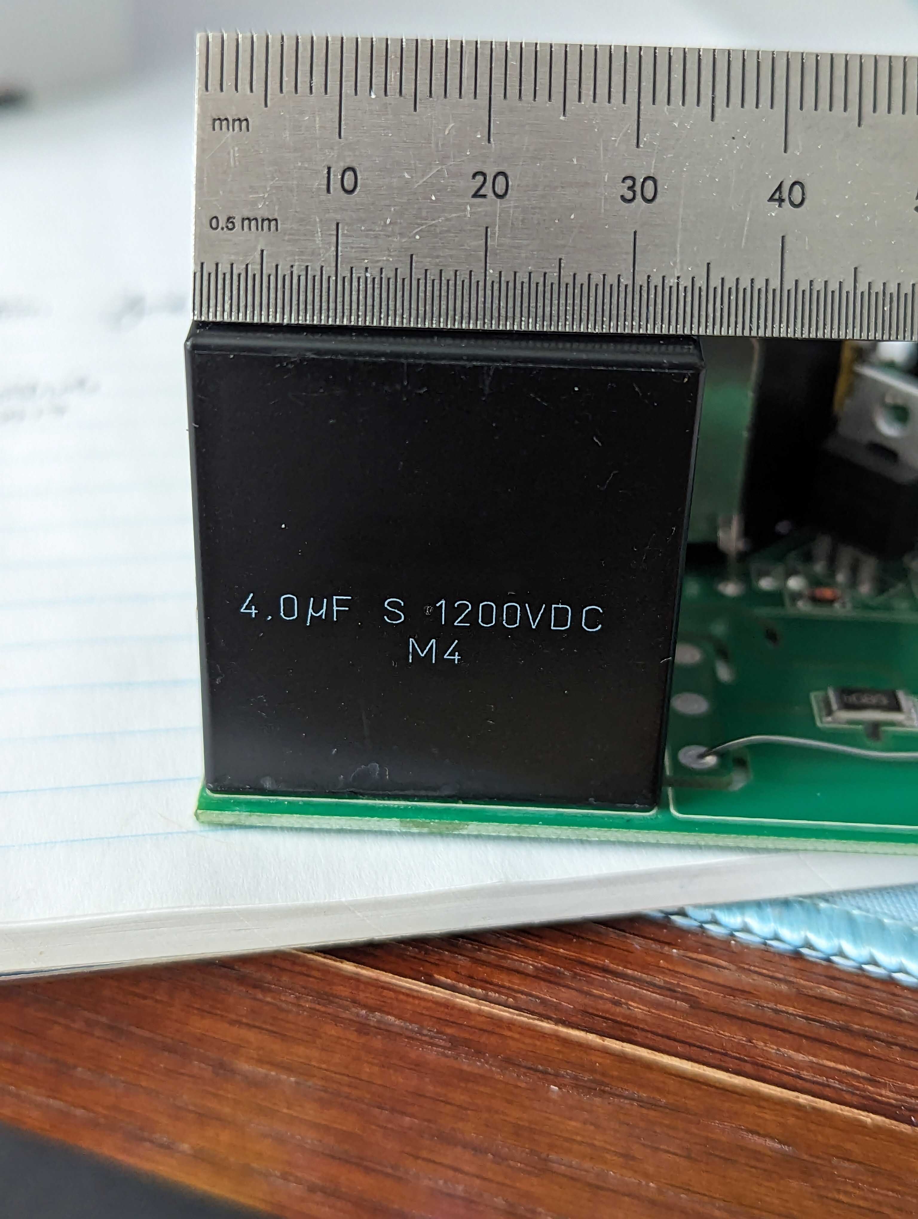
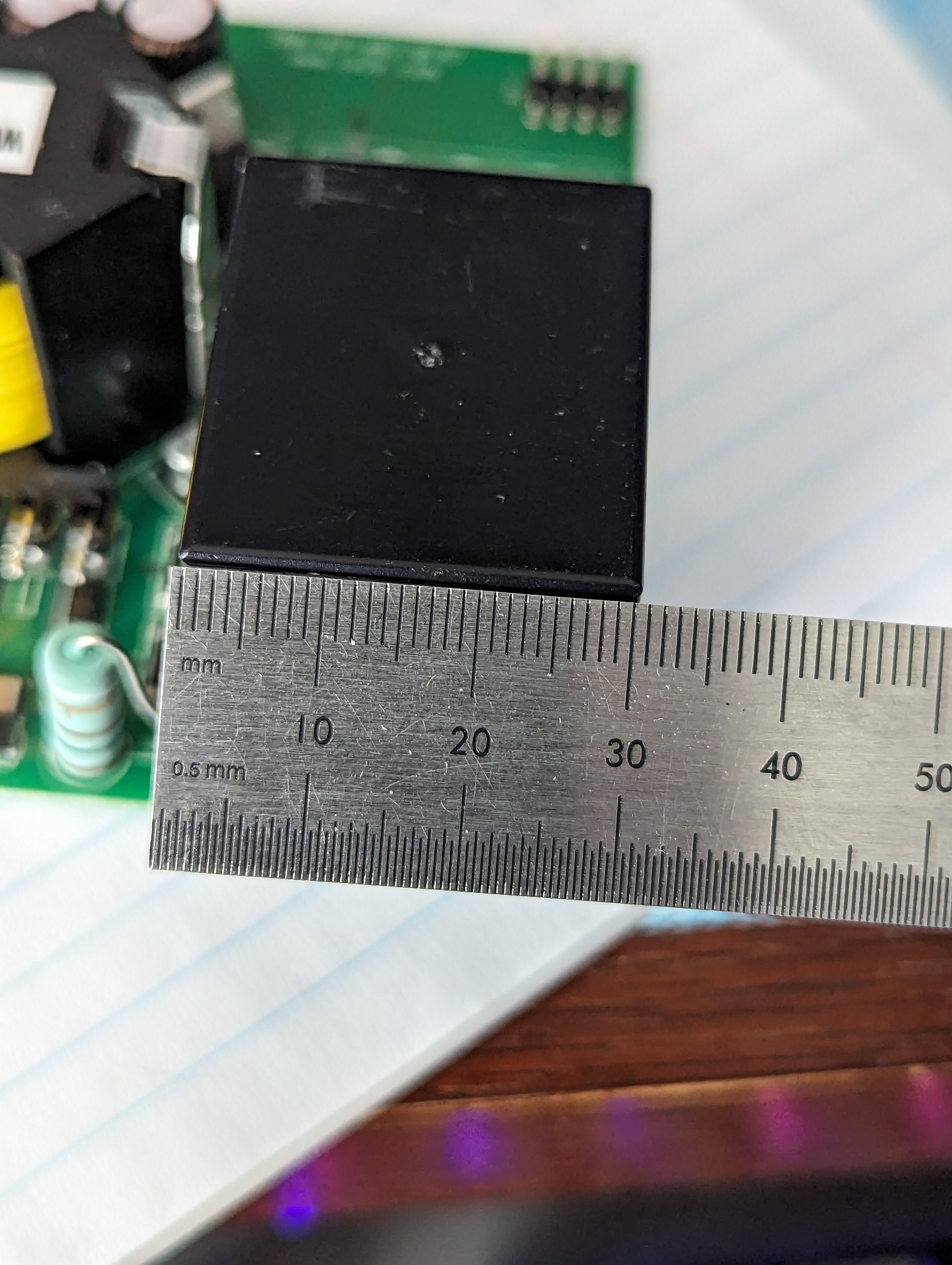
Hi, I've been unable to ID the pictured capacitor to track down a spec sheet or source. Do any of you folks recognize it? Pictured are two different capacitors that look to be identical except for slightly different markings.
239
240
241
242
243
244
245
246
11
How to properly size a serial bulb for protection when troubleshooting a circuit?
(discuss.tchncs.de)
247
8
[SOLVED] A pull-up resistor increases the low side of a signal, how can I counteract it?
(electronics.stackexchange.com)
248
249
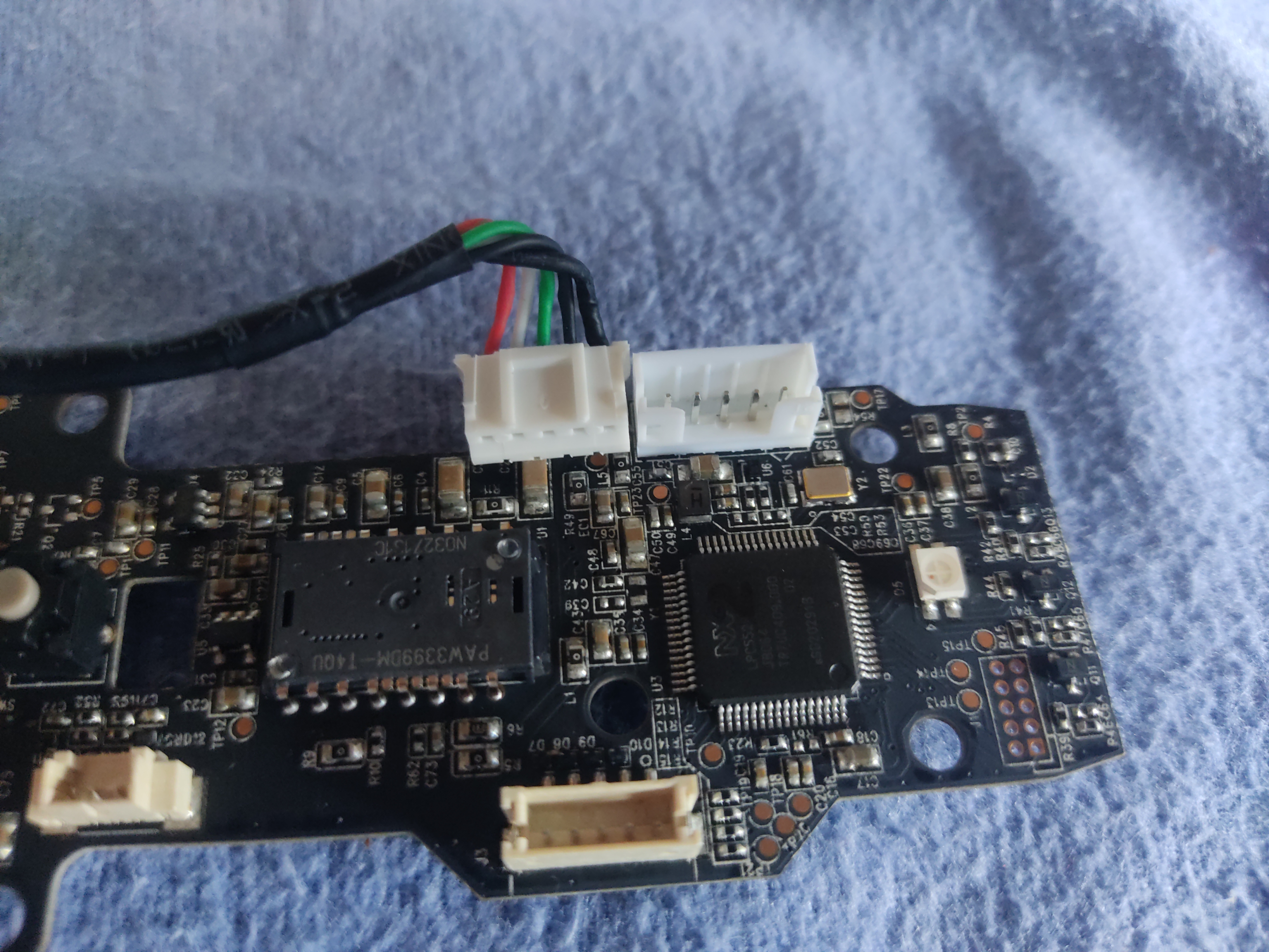
I'm working on adding extra access control to elevator calling buttons and i would like to identify the connector type of the wires connecting elevator buttons to the elevator panel
I have tried Micro JST 1.25MM 3-Pin Male & Female Connector Plug, it has the same Pitch Mating size of 1.25mm but unfortunately the connector itself is smaller than the original one.

250